Product documentation, build instructions and software for Enigma Uno, Enigma Z30, Mega Enigma and Pico Enigma, all of our Enigma Machine Simulators:
Thursday, December 31, 2099

Sunday, December 7, 2025
Experimenting with LoRa using the REYAX RYLR998 (Part 2)
This is how the transceiver nodes on the breadboard look like after adding a 7333 voltage regulator. A portable version with a touchscreen and fed from a 9V battery has been created.
You can read Part 1 here: https://arduinoenigma.blogspot.com/2025/12/experimenting-with-lora-using-reyax.html

In the previous post, it was determined that without a voltage regulator, the RYL998 would brown out the Arduino Nano. After a lot of research, we settled on a LDO (Low Dropout Regulator). The 7333 is an inexpensive part that can be fed 5V and it will produce 3.3V on its output.
The 7333 has two different pinouts. The following diagram shows the 7333A 3.3V voltage regulator:

And here is the circuit using the 7333B, the difference in the pinout is the location of the VIN and GND pins are swapped.

This circuit was prototyped on the breadboards, the modules reset to factory defaults using the AT+FACTORY command, reprogrammed with AT+ADDRESS=1 to have addresses of 1 and 2. One node was program to send data and the other one receives it. The nodes are stable at full transmit power even though one Arduino uses its 5V output to power the other node, so it it powering another Arduino and two voltage regulators. This proves the voltage regulators have enough built in margin.
The picture below shows the 7333 in the breadboard.

Once the circuit was proven on the breadboards, it was moved to a GIKFUN Prototype Shield ($15 for 3). It has the voltage regulator and the voltage divider to convert Arduino Software Serial TX from 5V to the 3.3V the 998 expects. The ICSP header with the long legs is needed for the SEEED Touchscreen and must be ordered separately, try searching for "6 PIN Double Row Straight Female PIN Header 2.54MM Pitch pin Long"

Here is the assembled node using an Arduino Uno, a custom shield and a touchscreen.

This shows the location of the antenna. The goal was to protect it against damage, but it may have been placed in a sub optimal location. The antenna is located between a metal part and the Arduino, a better location might be on the other side, using connectors, it can be extended out so it is exposed.

A sketch running on the handheld device was written to display a received message on the screen. A node in the breadboard sends AT+SEND=0,5,DATA! to the 998. The 998 on the shield receives the data and puts out on the serial port +RCV=1,5,DATA!,-17,11. The sketch on the handheld uses the first three characters to identify the receive command. Once the +RC command is received, the rest is displayed. The last two parameters, -17 and 11 show the Received Signal Strength Indicator (RSSI) and Signal-to-Noise ratio (S/N). The RSSI starts at 0 when the nodes are very close to each other and goes down. The S/N starts at 11 and goes down to -15. After a new message is received, the rectangle below the message toggles between red and green.

The breadboard was left inside a building and the handheld was taken out for a walk. The rectangle kept toggling between red and green while the RSSI and the S/N decreased. At 684 ft and with a signal strength of -111 and a signal to noise ratio of -15, it stopped toggling. The 684 foot range was through multiple buildings and trees.
How to convert the RSSI and the S/N to a cell phone style signal strenght indicator with 5 or 6 antenna bars? One idea is to disregard the S/N and convert the RSSI range of 0 to -111 to a range or 0 to 6 antenna bars. The other idea is to add the RSSI and the S/N together, it ranges from (0,11) to (-111,-15) and then convert to antenna bars.
Another experiment can be run by moving the module out so the antenna is exposed.
Next is to design a PCB and send it to Oshpark for manufacturing.
Source code is at https://github.com/arduinoenigma/REYAX-RYLR998-Tests
(To be continued...)
Tuesday, December 2, 2025
Experimenting with LoRa using the REYAX RYLR998
LoRa® is a radio technology that allows two nodes to send small volumes of data over long distances. An often quoted typical distance between two nodes with clear line of sight is 3-5km. This post started with some intellectual curiosity, what is the actual distance at which two LoRa nodes can communicate in an urban setting.
The ultimate goal is to have two battery powered handheld devices that use an Arduino Uno, a SEEED Touchscreen LCD and a LoRa module.
The initial goal is to have a base station node that receives LoRa messages and echoes them back, then a handheld node is configured to send a message every few seconds and if a matching response is received from the base station, an LED is lit. The handheld can be programmed to cycle through a few different messages.
To get there, the first step is to get two minimal LoRa nodes to communicate to each other.
Researching what LoRa modules were available on Amazon, the REYAX RYLR998 appeared as a viable candidate as it has 0.1 spacing pin headers, all it needs is power, ground, a serial port for communication and is very affordable at around $12.

Going out to the Internet for examples of how to use this device, variations on the following circuit started to appear. The diagrams used one Arduino Nano and one Reyax RYLR998 to send a signal when a button was pushed and another Arduino connected to another 998 to receive the signal and illuminate an external LED. Since we are trying to establish basic communication between two nodes and the Arduino has a built-in LED connected to pin 13, the transmit and receive node circuits were merged and simplified into the circuit below.
This circuit powers the Reyax 998 from the 3.3V pin on the Arduino Nano. Since the 998 is a 3.3V part, the circuit uses a 4.7K / 10K voltage divider to bring the 5V output of the Arduino TX pin down to a 3.3V signal that can be connected to the RX pin on the 998. The TX output of the 998 is 3.3V and can be connected and read correctly by the Arduino Nano. At the moment, the Nano is powered by the USB connector.

When the circuit above is wired and we try to program the Nano, the Arduino IDE cannot communicate with the Nano, the TX and RX pins of the Nano are connected to its own USB driver and to the 998 and they are clashing, resulting on the Arduino IDE being unable to communicate with the Arduino UNO,
A attempt was made to only move the 998 TX signal from the Arduino RX pin to Arduino pin 8, the logic here was the Arduino TX pin is an output and it can communicate with the RX pin on the USB driver chip as well as the RX pin on the 998, but the Arduino RX pin has two TX devices talking to it, the USB driver chip and the 998. This ended up allowing the Arduino to be programmed, the 998 received commands from the Arduino, but using the SoftwareSerial library to read pin 8 resulted in endless streams of +ERR=4 coming from the 998, indicating an Unknown Command error. It seems the 998 was not happy sharing the TX pin with the USB driver. Circuits that are shown sharing the TX and RX pins on the Nano are probably programmed with the 998 disconnected and then the computer is disconnected and the 998 connected.
Since the goal of this project is to make an Arduino Uno Shield, in the end, both the TX and RX pins of the 998 had to be moved to dedicated pins on the Arduino Nano and either the SoftwareSerial or AltSoftSerial libraries used to create a serial port in software. Both libraries work best when the Arduino pin 8 is RX and the Arduino pin 9 is TX. Pin 8 was directly connected to the TX pin on the 998. Pin 9 was connected to the 4.7k/10k voltage divider and its output connected to the RX pin on the 998. This circuit can be programmed reliably and communication between the Nano and the 998 is reliable.
The 998 factory defaults to 115200 baud and this is around the maximum the software serial port libraries can handle. The Arduino sketch in its initialization routine first opens the software serial port at 115200 baud, sends the AT+IPR=9600 to the Reyax998 then immediately closes the software serial port and reopens it at 9600. When this routine is executed on a factory default 998, it changes it default speed to 9600, if the speed is already 9600 baud, the AT+IPR=9600 command is disregarded as it is being sent at 115200 and the 998 is receiving at 9600. In practice, this mechanism works very reliably to change the default speed on a new device and is disregarded by an already configured module.
The reason the circuit below is labeled "DO NOT USE" is that when powered from the Arduino Nano 3.3V and the 998 is transmitting at factory default power levels, it can cause the Nano to brown out. The factory datasheet says the 998 may consume 140mA when transmitting. Sources say the Nano 3.3 pin can only provide 50mA and some of that is needed for the USB driver chip. A separate 3.3V power regulator is needed and has been ordered. While this arrives, the AT+CRFOP=4 is used to bring the transmission power down. With the transmit power dialed down, the circuit below sends and receives data reliably to another node that is in close proximity.

All of the 998 configuration parameters are saved on an internal EEPROM. It seems one use case the manufacturer envisions is to connect the Reyax 998 to a computer using a USB dongle and send all the configuration commands using a terminal program, then move it to a host circuit that uses just to send and receive data. We are using the Arduino Nano to issue the configuration commands, getting input from the user for parameters such as Node ID, Network ID and Encryption Password.
The breadboard below shows two independent LoRa nodes using the circuit above. The jumpers are ELEGOO 20cm Multicolored Dupont Wire, at $7.00 for 120 (40 F-F 40 M-F 40 M-M), a bit long, but fit snuggly on the breadboard.
The resistors used for the voltage divider are 1/8W and the legs are quite thin, a trick to make them fit more snuggly into the breadboard is to bend the tips back, flatten that with pliers and insert the doubled up pin into the breadboard.

Next is to publish the source code at https://github.com/arduinoenigma/REYAX-RYLR998-Tests
The manufacturer datasheet can be accessed at https://reyax.com/upload/products_download/download_file/LoRa_AT_Command_RYLR998_RYLR498_EN.pdf
Manufacturer webpage: https://reyax.com/products/rylr998/
(To be continued...)
Read Part 2 to see the working circuit with separate 3.3V regulator here: https://arduinoenigma.blogspot.com/2025/12/experimenting-with-lora-using-reyax_7.html
Saturday, February 22, 2025
Daniel Palloks Universal Enigma Simulator has moved
Daniel Palloks Universal Enigma Simulator has moved to
Universal Enigma is a proven accurate simulator that implements lots of machines, including the lever stepping Enigma I, M3, M4, Norenigma, S, D, K, Swiss K, Rocket, Tirpitz and the geared A28/G31, G-111, G-260, G-312, G-401
The homepage has links for Swedish Enigma-B, which had special 28 contact wheels in order to support the additional letters in the Swedish alphabet.
There is also a link to the numbers only Enigma Z.
The simulators are very lightweight HTML wise and can be saved locally to the users computer.
This is an invaluable resource if you are developing any kind of Enigma program.
The new homepage is available at:
The German homepage is at:

Universal Enigma Simulator

This is the list of machines the Universal Enigma implements:

Sunday, December 1, 2024
CAN Bus Tool
Product Pictures And Documentation Showing The Usage Of The CAN Bus Tool

Messages can be viewed in real-time or specific messages can be filtered by message identifier and message content. The bus speed can be dynamically changed to the following speeds: 5, 10, 20, 31. 25, 33, 40, 50, 80, 100, 125, 200, 250, 500, and 1000 kbps (1Mbps).
The unit, in Normal mode, will send acknowledgment replies to each received message or it can be configured in Silent mode as Listen-Only and not send replies. There is a built in 120 ohm termination resistor that can be enabled and disabled with a jumper.
In Silent mode with the 120ohm termination resistor disabled, this unit is invisible to other devices in an existing bus.
Sunday, July 7, 2024
Updates to Dual Screen DSKY

Several usability improvements have been made to the Dual Screen DSKY
Webpage changes:
1) The launch.cmd and launch-edge.cmd batch files have been modified to attemp to terminate the browser process if it is running in the background as exiting the browsers may leave processes running on the background and we need to start the browsers from scratch in order to use the special flags that allow Serial.IO to run
2) If the connection to the external DSKY is lost or it is unplugged, the "Disconnect" button changes back to "Connect" and now it is possible to re-connect without refreshing the page and losing the mission progress
3) The status of the left screen indicators are now only sent to the external DSKY if they have changed, with a complete refresh being periodically sent. Previously they were all being sent continuously and generated too much serial port traffic.
DSKY Changes:
1) A circular buffer has been implemented in the Arduino Mega. Incoming characters are received, buffered, and released on a timer to the screens. Previously some commands were lost if a lot of changes were being drawn on the screens.
The software can be downloaded at:
Wednesday, March 9, 2022
Cipher Machines and Cryptology has moved
Dirk Rijmenants (drdefcom) Cipher Machines and Cryptology has moved from it's long time address at telenet.be to its own domain.
https://www.ciphermachinesandcryptology.com/
This move was announced in the Enigma World Code Group Forum
https://enigmaworldcodegroup.freeforums.net/thread/266/cipher-machines-cryptology-moved
If you are looking for the Enigma Simulator or the Enigma Codebook Generation tool, those can be downloaded at the links below:
www.ciphermachinesandcryptology.com/en/enigmasim.htm
www.ciphermachinesandcryptology.com/en/codebook.htm
There is also a blog at:
https://rijmenants.blogspot.com/
Want to read more? Here is a page with a lot of information on the Enigma Machine and Cryptology. (H/T E.K.)
https://www.emissary.ai/the-encrypted-text-of-enigma-machines/
Sunday, July 25, 2021
Setting Up Arduino IDE to Compile Dual Screen Apollo DSKY Sketches
Here are the instructions to setup an Arduino IDE to successfully compile the source code for the Dual Screen Apollo DSKY and other Arduino sketches that use the GPIO fast pin library and/or the FastSeedTFTv2 graphics library for the Seeed TFT Touch Shield v2
For more information on the Dual Scrren Apollo DSKY:
https://arduinoenigma.blogspot.com/p/dual-screen-apollo-dsky.html
To update the arduino sketches:
The Arduino IDE must be installed first. This is generally an uncomplicated step that involves downloading the appropriate software from the Arduino website:
https://www.arduino.cc/en/software
The next step is to download the zip files for the following three projects, direct links to the zip files can be found below, all links open in a new window:
Project pages:
https://gitlab.com/arduinoenigma/dualscreendsky
https://gitlab.com/arduinoenigma/Arduino-GPIO
https://gitlab.com/arduinoenigma/FastSeedTFTv2
Direct links to the zip files:
https://gitlab.com/arduinoenigma/dualscreendsky/-/archive/main/dualscreendsky-main.zip
https://gitlab.com/arduinoenigma/Arduino-GPIO/-/archive/master/Arduino-GPIO-master.zip
https://gitlab.com/arduinoenigma/FastSeedTFTv2/-/archive/master/FastSeedTFTv2-master.zip
If prompted, save all the zip files to your Downloads folder, which should look like this:
Saturday, July 10, 2021
Setup Instructions for Dual Screen Apollo DSKY

For more information on the Dual Scrren Apollo DSKY
https://arduinoenigma.blogspot.com/p/dual-screen-apollo-dsky.html
To use with a computer:
1) Install Arduino Virtual Serial Port Drivers.
To function properly, the DSKY needs the Arduino Serial Port drivers installed in the host computer. If there is any version of the Arduino Software installed on the computer, this step can be skipped.
If the Arduino Software is not installed, download it from:
http://arduino.cc and click on the "Software" button on the bar at the top of the screen
or for a direct link to the English version:
https://www.arduino.cc/en/software
Follow the instructions for your operating system to install it.
2) Connect Arduino Mega on back of DSKY to host computer.
Once the Arduino Software has been installed, it is time to plug in the DSKY so it gets assigned a serial port number.
There are three Arduinos on the DSKY. The Two Arduino Nano in the front are only used to drive the Screens, they are not connected to the host computer except to modify the programs (sketches) running on them.
Flip the DSKY and connect the USB cable to the large Arduino Mega on the back. Connect the other end of the cable to the host computer.
The host computer will install the serial port drivers and assign a serial port number to the Arduino Mega. Communication can be verified by launching the Arduino Software. Click Tools -> Board -> Arduino/Genuino Mega or Mega 2560. Click Tools -> Port and select the newly created port. Click Tools -> Serial Monitor and on the bottom right of the screen, select 9600 baud. On the Top Line of the Serial Monitor type A and press Send, the "UPLINK ACTY" indicator should illuminate. Type Q and press Send and the "COMP ACTY" indicator should illuminate. Sending lowercase a and q will turn those indicators off. Exit the Serial Monitor, otherwise MoonJS cannot connect to an open serial port.
3) Install modified copy of MoonJS on host computer.
Download SerialMoonJS from:
https://gitlab.com/arduinoenigma/serialmoonjs
A direct link to the software is here:
https://gitlab.com/arduinoenigma/serialmoonjs/-/archive/master/serialmoonjs-master.zip
Unzip the file to a folder in the host computer.
4) Launch MoonJS and Connect to DSKY Serial Port.
Ensure the DSKY is first plugged in to the Arduino Mega port before launching MoonJS
Navigate to the folder where SerialMoonJS was unpacked.
The modified MoonJS software uses WebSerial, which runs on Chromium based browsers if a special command line flag is used when launching the browser.
There are two launchers included in the zip file
LAUNCH.CMD opens SerialMoonJS using Google Chrome
LAUNCH-EDGE.CMD uses Microsoft Edge
Other Chromium based browsers may be supported, the command line parameters are:
--allow-file-access-from-files --enable-experimental-web-platform-features
The first one is needed to allow html files to open files in the local computer. The second one enables WebSerial and a host of other experimental features.
Needless to say this is not the most secure browsing environment, so a browser in this state should not be used to browse the web.
Click either on LAUNCH.CMD or LAUNCH-EDGE.CMD
The launcher makes sure the browser is installed and not currently running, showing error messages if either of those conditions are detected.
A final warning message to not use this browser on the open internet is displayed before proceeding to MoonJS, the AGC simulator.
Once MoonJS launches, click on the "Connect" button on the top right side of the screen. A new dialog box will show a list of serial ports, select the "Arduino Mega 2560"and click the "Connect" button on the dialog box.
The screens on the external DSKY should update to match what is shown on the computer. To verify connectivity, on the external DSKY press: VERB 3 5 ENTR
A displays will show a flashing selft test on both the host computer and the external DSKY.
If the USB cable is disconnected without clicking the "Disconnect" button first, the page must be reloaded before being able to click the "Connect" button again.
To use MoonJS, click on the "Launch checklist" link on the top left of the screen and follow the instructions.
press V37E00E
click on "Enable IMU"
press V91E
press V35E
press PRO, repeat until NO ATT turns off
press V37E01E
when PROG changes to 02, click on "Launch"
(optional) Manual Control of External DSKY
follow the instructions above to use Serial Monitor to connect.
The left screens uses upper case A B C D E F G H I J K L M O to turn on each indicator, a lower case letter turns the indicator off. The right screen uses Q to turn the COMP ACTY indicator on. send P99 to display the PROG indicator, V99 displays the VERB indicator, N99, displays the NOUN indicator. The bottom three lines are controlled with X+88888 Y-99999 and Z300000. The first character of the X Y and Z commends must be a + or - anything else gets ignored. Press keys on the external DSKY and they will be shown in the Serial Monitor.
If you have made it this far, try pressing the NOUN key and without releasing it, press the RSET key.
Sunday, May 16, 2021
How to use PicoEnigma, an Enigma Z30 Simulator
PicoEnigma is an Enigma Z30 simulator, a rare, numbers only Enigma Machine.
Its mode of operation is similar to other Enigma machines, it has a keyboard and a lampfield, pushing a key sends electricity to the entry rotor (ETW), then the electricity goes from right to left through the rotor pack, comes back through the reflector (UKW), and returns from left to right through another set of wires in the rotor pack, goes into the ETW and out to a lamp.
In this machine, the rotors can be rearranged, the ring setting can be changed and the rotor starting position can be set. To successfully decrypt a message, the machine settings must be the same used to enctypt it.
This simulator is designed to operate the same as the Enigma Z30 Simulator for the KIM Uno:
https://arduinoenigma.blogspot.com/p/enigma-z30-for-kim-uno.html
After the simulator is turned on, it is ready to encrypt a message. The rotor starting position is 4321. Pressing a key advances the rotors and lights the result. The result will be illuminated while the key is being pushed. Releasing the key turns the lamps off.

During machine operation, all the lamps will be off if none of the black keys are pressed, or one lamp will illuminate when a black key is pressed. Pressing the red key enters the configuration mode. To indicate at a glance that the machine is in the configuration mode, all of the lamps are lit except for one.
When only the first lamp is turned off, the rotor types are being changed. Pushing the keys above or below the displays changes the rotor type for that position. Each rotor can only be used once. Once a unique rotor combination is selected, pushing the red key again advances to the next setting.

When the second lamp is turned off, the ring settings are being changed. The up and down keys are used to change this setting, Each rotor can be set differently to a number from 0 to 9. Pressing the red menu key advances to the next setting.

When the third lamp is turned off, the stepping mode is being changed. There were two kinds of machines, one with a traditional lever stepping and another with geared stepping. The lever stepping machines suffered from a double stepping anomaly where a 9 in any position steps that wheel and the one to its left. A double stepping sequence is: 0088 0089 0090 0101 Geared stepping works like a car odometer and no digits are skipped.
The stepping mode is indicated by the digit on the right. If it shows a 0, the machine is using lever stepping, if it shows a 1, it is using geared stepping. In this screen, pushing the leftmost up and down button also changes the brightness of the lampfield digits.

Pushing the red menu button again turns all the lamps off and returns to the operating mode screen.

Pushing the up and down buttons changes the rotor starting position. The machine is now ready to encrypt numbers.
To send a text message, an encoding scheme must be devised. Either substitute letters by two numbers A 01 B 02 ... Y25 Z26 or use a codebook where words are substituted by numbers, first translate the message to numbers then encrypt the numbers.
To decrypt the message ensure the machine is set up exactly as the machine used to send the message. Ensure the starting position is set the same as well.
For example, to encrypt the message TEST, use the table below.
A B C D E F G H I J K L M
01 02 03 04 05 06 07 08 09 10 11 12 13
N O P Q R S T U V W X Y Z
14 15 16 17 18 19 20 21 22 23 24 25 26
The word TEST would be encoded as 20 05 19 20
Typing and holding one number at a time in the machine using the default settings after power up yields 44 57 43 94
The wheels should be at position 4329 after all the numbers have been typed.
To decrypt it, use the up and down keys to reset the wheels to the starting position of 4321. Then type the encrypted message (44 57 ...) and the original message (20 05 ...) will be displayed.
Thursday, January 21, 2021
Dual Screen DSKY talks to host computer via Virtual Serial Port
This is a new project, a DSKY, the Display Keyboard interface for the Apollo Guidance Computer (AGC), using two 240x320 LCD screens and a keypad made with Kailh Cherry clone keys.
This DSKY uses an Arduino Mega 2560 to interface with the host computer via a USB Virtual Serial Port. The Arduino Mega uses two of its auxiliary serial ports to communicate with the Arduino Nano on each screen. The Arduino Mega is also responsible for scanning the DSKY keyboard and sending keypresses back to the host computer.
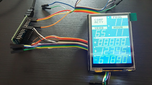
Each indicator on the left and right screen is controlled by a command from the host computer. For example to illuminate the indicators below, the host computer sends to the Mega the following string "C F P V00 N00 X 00000 Y 00000 Z 000 ". The Mega receives commands from the host computer and forwards them to both screens. The left screen reacts to single character commands A..O. Upper case commands illuminate an indicator, lower case commands turn them off. The right screen uses the Q command to illuminate the COMP ACTY indicator and the P, V, N, X, Y, Z commands to display numeric data which may include a leading positive or negative sign.

This DSKY is being made to interface to a modified version of Moonjs, An Online Apollo Guidance Computer (AGC) Simulator (https://svtsim.com/moonjs/agc.html). The simulator has been modified to use the experimental Web Serial API available in the Google Chrome browser in order to both send screen data to the external DSKY as well as be controlled by keypresses from the external DSKY.
The modified simulator accepts keypress commands from the external DSKY via Serial Port. The commands correspond to the first letter of each key legend. For example if KEY REL is pressed in the external DSKY, it sends K to the simulator. Thus, to calibrate the IMU as part of the launch checklist, the simulator receives V 3 7 E 0 1 E from the external DSKY.
The modified simulator is available at https://gitlab.com/arduinoenigma/serialmoonjs

A PCB is being designed to hold both screens and the keypad. Each screen connects to an Arduino Uno compatible pin header and is controlled by an Arduino Nano located under it. The Arduino Nano has been rotated so the USB connector is accessible Only the minimum number of signals needed to control the display using SPI have been routed from the Nano to the LCD screen pins. The RX pin on each Nano is connected to a separate auxiliary TX pin on the Mega.
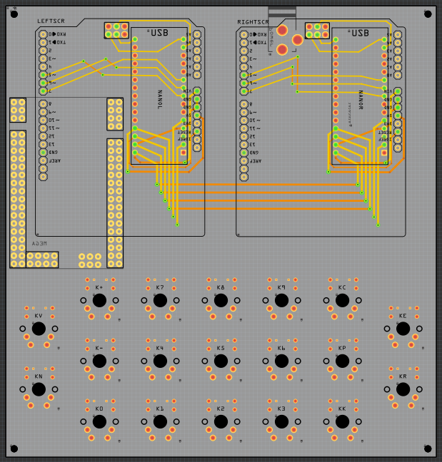
The minimum number of signals needed to control the SPI LCD screen was experimentally determined by using jumper wires.
Here is an OSHPark (https://oshpark.com/profiles/ArduinoEnigma) rendering of the board design so far:


Friday, December 18, 2020
Enigma Machine PCB Rotor Wheels now available
A complete set of Enigma Machine PCB Rotor wheels for a three rotor machine is now available at the link below:

Sunday, October 25, 2020
UHR Switch Bill Of Materials (BOM) and Assembly Instructions
For more information about the UhrSwitch:
Bill of Materials:
1) 1x UHR Switch PCB
2) 1x Meduino, (Mega 2560 Pro Mini). Make sure the pins to the right and the left of the USB connector match
https://www.ebay.com/sch/i.html?_nkw=meduino
3) 2x 0.56 inch RED 7 SEGMENT LED DISPLAY COMMON CATHODE. Get either 2x 5161AS or 2x 5611AH
https://www.ebay.com/sch/i.html?_nkw=5161as
5) 1x Potentiometer Cap (you may want to substitute with something more appropriate)
https://www.ebay.com/sch/i.html?_nkw=potentiometer%20cap%206mm%20inside
7) 20x 0.5M Audio Cable 3.5mm Male to Male 90 Degree Angle. Get the 0.5M the 20cm is too short.
8) 4x M2 25mm Female to Female Brass Standoff
https://www.ebay.com/sch/i.html?_nkw=M2%2025mm%20Female%20to%20Female%20Brass%20Standoff
9) 4x M2 6mm Plastic Screw (Black)
10) 4x M2 6mm Brass Screw
11) 1x 3 Pin PCB Mount 5.5x2.1mm Female DC Power Jack Socket Connector
https://www.ebay.com/sch/i.html?_nkw=3%20Pin%20PCB%20Mount%205.5x2.1mm%20Female%20DC%20Power%20Jack%20Socket%20Connector
https://www.ebay.com/sch/i.html?_nkw=3%20Pin%20PCB%20Mount%205.5x2.1mm%20Female%20DC%20Power%20Jack%20Socket%20Connector
Component Pictures:


Assembly Steps:
Read all of the assembly steps and look at the pictures at the bottom before starting any soldering. The components can be placed in the PCB before soldering them in order to verify that everything fits and is on the correct layer. Start soldering only once everything is understood.
Identify Top and Bottom sides of PCB.
Top: only shows EXT and INT words in white
Bottom: Flag, word UHRSwitch
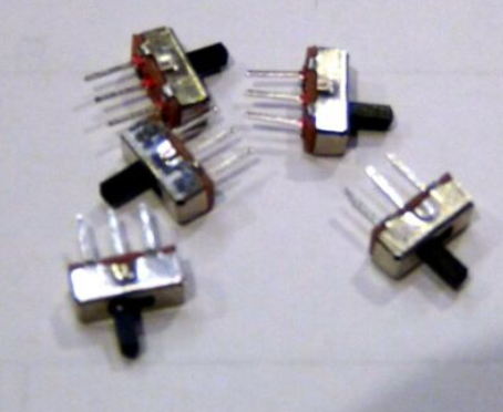
-Insert power switch on 3 pin header next to the words EXT and INT on top side of PCB and solder it.
-Insert 2x seven segment displays on headers on top side of PCB and solder them
-Insert ENC11 Rotary encoder on top side of PCB and solder it
-flip PCB to bottom side
-Insert pin headers for Meduino into bottom side of PCB. Insert the short end of the header pins into the PCB so they do not protrude too far out the front side. Flip the PCB and place on a flat surface. Solder pins on front side of PCB. Be careful not to touch the side of the seven segment displays with the soldering iron.
-Flip PCB and insert Meduino onto long side of pin header on bottom side of PCB. Solder it
-Insert PCB Spacer on DC Power Jaack and Insert Jack into bottom side of UHRSwitch PCB. The role of the Spacer is to keep the DC Power Jack pins from protruding too far out the front side of the PCB. Solder the Power Jack.
-Flip PCB to top side.
-Insert audio cables into holes on PCB from top side. The tails of the cables should point down, away from the seven segment displays.
-Flip PCB to bottom side.
-Solder one spot from the audio cable plug to the PCB.
-Once all soldering is completed, sand down any mouse bites sticking out the sides of the PCB.
Assembled Unit Pictures:


Subscribe to:
Comments (Atom)