The design of the board is almost ready for production. It's been fully routed, all the connections verified, a routing mistake has been found and fixed and the mounting holes are in their final location. All that's left to do before production is some more double checking and cleaning up the bottom silkscreen. Still waiting on the 16 segment displays to arrive, so there is time to check this.
We have the opportunity to do the vias under a key trick again. It is harder to hide all the copper by routing it on the bottom layer on this design, and there are a couple of vias in the display area that are not hidden under a display module. Let's just think that all of these imperfections give this board some character.
A routing mistake was found on the menu button located below the enigma logo. It was wired to the exact same select line/return line combination as the B key, so if unfixed it would have registered as pressing B.
The fix was simple, the select line above the existing via was unused. All that was needed was to move the via to the next select line. The fix in Fritzing was easy: right click on the bottom wire going from the button to the via and "Delete Wire", right click on the via "Convert Via to Bendpoint", right click on the bendpoint, "Remove Bendpoint". Then create a bendpoint on the next wire, right click on the bendpoint "Convert Bendpoint to Via", drag a wire on the bottom layer from the button to the newly created via and use the parts inspector to set it as "Super Fine (8 mil)" on the bottom layer.
The resulting fix:
Here are the pin assignments. The 17 pins used to control the display segments are also used to read the keyboard using the KEY1L, KEY2L and UPDNL input pins used as sense lines. This layout allows keys on different sense lines to be pressed simultaneously without corrupting the display. Any single button on the keyboard can be pressed simultaneously with the up/down buttons used to change the rotors. This gives an extra measure of realism by allowing some of the wiring checking procedures on the Merkblatt to be performed.
The silkscreen labels on the bottom layer need to be cleaned up. This will probably be done last.
Here is the top copper layer. Mostly horizontal lines. The angled lines going to the six lamps on the bottom right stay clear of the silkscreen labels. Six vias are visible on the display area. There will of course be tented. These vias will probably disappear under the shadow of the displays.
Most of the routing action is happening on the bottom layer. To get this clean routing, the board was wired in the following order:
0) layout the components, giving the keyboard and lampfield the characteristic diagonal slant. Place the displays and the up/down select buttons on the right side of the display they control. Place the Arduino Mega 2560 Pro Mini on the top right corner of the board and place a menu button on the top right corner as well.
1) connect the bottom pins of the keys using the top layer
2) connect the bottom pins of the LEDs using the top layer
3) connect the common pins of the up/down select keys using the top layer
4) connect each pin of the (4) 16-segment displays together on the top layer. Weave the traces around and through the display pins. Do not connect the common pins on each display. Those will be individually run later.
5) on the bottom layer, using vertical lines, connect a lampfield LED to the corresponding button in the keyboard (Q light to Q key, W lamp to W key...).
6) on the bottom layer, connect the bottom pins of the top two LED rows together (single trace going from Q to A. This works out to 17 LEDs on one common pin (LED1L).
7) on the bottom layer, connect the bottom pins of the top two keyboard rows together (Q to A again)
8) Starting with pin 2 (leave pins 0 and 1 unused so the Mega2560 serial port works), run traces on the top layer from each of the display pins to the Arduino.
9) Using the bottom layer, connect each LED on the top two rows to individual segment pins on the seven segment displays.
10) Using the bottom layer, connect each LED on the third row to individual segment pins on the seven segment displays.
11) The six LED on the bottom right of the lampfield were too far away from selection lines and long horizontal lines with slants at the end were run on the top layer. The traces are kept away from silkscreen legends. Once those horizontal traces are closer to the left edge of the board, they are run vertically using the bottom layer to the selection lines. Some of the vias are hidden under the displays.
12) Using the bottom layer, route the 2 common sides of the lamp field leds (LED1L, LED2L) and the 2 common sides of the keyboard (KEY1L, KEY2L) to the Arduino. The common side of the Up/Down select buttons (UPDNL) was too close to Arduino pin 46 and was wired horizontally at this point.
Now, all the LEDs and buttons on the main board are wired and this is a functional simulator. By observing the vertical on bottom layer /horizontal on top layer discipline, plenty of space around vertical traces exists to run individual pins to the plugboard connector at the bottom of the board. It is just a matter of selecting a group of 5 or six pins on the Arduino and planning how to route them to the single row connector at the bottom without crossing wires. At some point, we ran out of space to run plugboard wires without using the top layer. A spot was selected under the G key to place a few vias and cross to the other side of the board.
The last thing to do is find a spot to solder the battery wires, the power switch and connect them to the VIN/GND pins on the Arduino.
And by methodically breaking down this task into simple manageable steps, this board is hand routed.
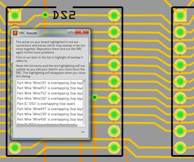
This is how the displays are interconnected. The DRC is not entirely happy with the traces going in between pins, but as long as the red spots look minimal like that, this will manufacture ok.
The holes are placed to support 3mm standoffs. Since board size costs $$$, there is no extra blank space around. The board will sit inside the enclosure walls, not on top.
After a talking to fellow Enigma Simulator Designer @lpaseen (
www.meinenigma.com), transient suppression diodes were incorporated into the design of the board. Attention was paid to not placing solder joints on the plug labels.
One of the last steps is to determine that every pin on the Mega2560 is connected to a single pin on the display, a single Up/Down key, and a single LED (which in turn connects to a single key in the keyboard).
The common lines running across the bottom of the LED and keys go into individual pins on the Arduino,
Arduino pin 18 drives Display pin 10 (segment D2, the down key on the rightmost display, LEDs Z, and B, keys Z and B (not shown).
Arduino pin 27 serves as the common (LED1L) for the leds on the top two rows.
Next, map the plugboard connections, double check some more and hit submit...