Sunday, May 31, 2020

Designing an UHR Switch for an Arduino based Enigma Machine Simulator

This article will explore some considerations when designing an UHR switch for a modern microcontroller based Enigma Machine Simulator.

The UHR Switch was an external attachment to the Enigma Machine. It is the small square device to the right of the Enigma Simulator shown below.


The UHR Switch connects to the plugboard and performs different substitutions depending on which of the 40 possible values is selected by using the rotary encoder on its face. 


The UHR Switch has 20 plugs, labelled 1a 1b 2a 2b 3a 3b .. 10a 10b.

A typical Enigma Code Sheet would list the 10 plugs to be installed as follows:
QP WY EX RC TV ZB UN IM JK OL

When using an UHR Switch, plug 1a would be connected to Q, 1b to P, 2a to W, 2b to Y, 3a to E, 3b to X, ending with 10a to O and 10b to L. Normally, a plug would substitute Q to P and P to Q, but the UHR switch may break that symmetry depending on the setting used. For compatibility with machines not using it, position 0 performs the same symmetric substitution as the plugs Q to P and P to Q. Positions that were multiples of 4 (4,8,12...) perform different symmetric substitutions, for example, position 4, as wired above would substitute Q to B and B to Q.

The image below, found under the Wiring section of the CryptoMusum UHR article, describes the input and scrambler disk wiring.


The link below lists all substitutions produced by the UHR. It can be used to verify the correctness of an implementation


UHR:6
abcdefghijklmnopqrstuvwxyz
aotdxfghbvewrjczmyspnqkiul
1a->8b  7b->9a
2a->9b  1b->6a
3a->3b  8b->4a
4a->2b  6b->10a
5a->1b  2b->7a
6a->10b 9b->3a
7a->7b  5b->1a
8a->6b  3b->8a
9a->5b  10b->2a
10a->4b 4b->5a

The enigma machine uses the plugboard twice for each letter encoded. When a key is pressed, it first goes through the plugboard to be either substituted by another letter or be left alone. Then it goes into the rotor pack, through the reflector and back trough the rotor pack to be encoded into a different letter. Lastly, it goes through the plugboard again before going to the lampfield. 

A microcontroller implementation of an Enigma Machine with a plugboard would perform all of the steps above. Typically, all 26 plugs would connect directly to a microcontroller with sufficient I/O pins or to an IO port expander. Either way, each pin needs to be bi-directional and can be used as an output or an input. When used as an input, an internal 10k pull up resistor can be activated so the port will read 1 if not connected to anything. 

To see if a plug is installed, first all the ports are switched to input and the internal pull up activated, then the port corresponding to the letter to be substituted is switched to output and driven low. One by one all the other ports are read, if a plug is not installed, it will read as 1. If a plug is installed, another port will read 0. If all the other ports are read and neither returns 0, a plug is not installed and that letter is not substituted. 

This behavior is performed twice, once when a key is pressed to see if it needs to be changed on the way to the rotor pack and once more as it comes out of the rotor pack to determine the letter to illuminate in the lamp field. 

Let's use Daniel Palloks Universal Enigma to analyze how the UHR works. A default M4 machine with B reflector and Beta thin wheel has been selected. The following plugs have been installed QP WY EX RC TV ZB UN IM JK OL. The plugboard has been activated and UHR has been set to position 06


The first two lines in the signal monitor show the substitutions performed by the UHR.

         abcdefghijklmnopqrstuvwxyz    top
         aotdxfghbvewrjczmyspnqkiul    bottom

these can be expanded using the actual plug substitutions listed above (1a->8b) as shown below:

         11 22 33 44 55 66 77 88 99 00
         ab ab ab ab ab ab ab ab ab ab
Plugged: QP WY EX RC TV ZB UN IM JK OL top 
Uhr: 06  MZ KU XI YT PQ LO NJ BR VE CW bottom
         86 97 38 25 11 00 79 64 53 42
         ba ba ba ba ba ba ba ba ba ba
                    
Lets press A:


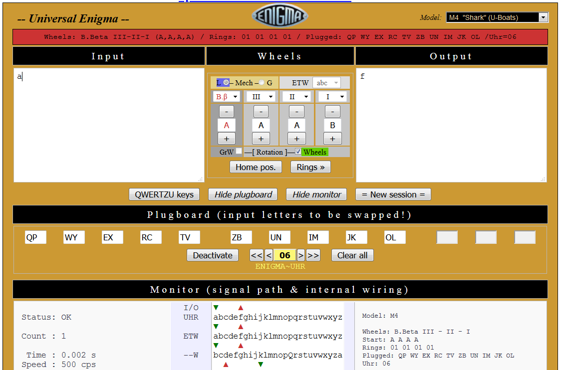
The arrows indicate the direction the signals are traveling. The topmost green arrow going down into A shows the keyboard going into the UHR, since this letter is not plugged, it goes into the ETW, the entry rotor as itself. It comes out of the rotor pack as F, and again, this letter is not wired to the UHR, so it goes out to the lamp field as itself.

Now lets press A again.


It goes in as A, an unplugged letter, so it goes into the rotors as A, comes back out as T, a plugged letter and the UHR performs a bottom to top lookup and goes out to the lampfield as C.

Now lets press a plugged key, P:


It goes in as P, a plugged letter and the UHR performs a top to bottom lookup, sending it into the rotor pack as Z. It goes through the rotors and comes out as A, an unplugged letter, so it continues as an A to the lampfield..

Lastly, lets press P again:


It goes in as P, a plugged letter and the UHR performs a top to bottom lookup, sending it into the rotor pack as Z. It goes through the rotor pack and comes out as O, a plugged letter and the UHR performs a bottom to top lookup and goes out to the lampfield as B.

Now, lets press P until the green arrow going from the keyboard into the UHR and the red arrow coming from the rotors out into the UHR align:


P gets translated by the UHR as Z when going from the keyboard into the rotors and the resulting P gets translated by the UHR as T when going out from the rotors into the plugboard.

And this is the point where one realizes that a software implementation of the UHR switch on a simulator that has a plugboard with a single plug per letter is not a straightforward task. The UHR needs to know whether the signal is going into the rotors or coming out of the rotors.

The real enigma machine uses two connectors per plug, A normal wired plug crosses the top connector on one side to the bottom connector on the other side and vice versa. The plug has an internal shorting bar that connects to top connector and the bottom connector. The plug pushes that shorting bar with an insulated tip and connects the top and bottom of one letter to the bottom and top of another letter. The UHR connects the top side of the plugs to the bottom side of the plugs using the A and B connectors. 

A software UHR with single connector per letter needs to somehow differentiate whether the signal is going into the rotors and it needs to perform a top to bottom translation or it is coming out of the rotors and into the UHR and it needs to perform a bottom to top translation. 

The different substitutions have been highlighted below. The entry substitution is the highlighted P on the top left side of the diagram, that gets translated through a top to bottom lookup into a Z. The exit substitution is the highlighted P on the bottom right part of the diagram, that gets translated through a bottom to top lookup into a T.

         11 22 33 44 55 66 77 88 99 00
         ab ab ab ab ab ab ab ab ab ab
Plugged: QP WY EX RC TV ZB UN IM JK OL top 
Uhr: 06  MZ KU XI YT PQ LO NJ BR VE CW bottom
         86 97 38 25 11 00 79 64 53 42
         ba ba ba ba ba ba ba ba ba ba

Another thing to keep in mind is that the UHR does not see all the letters being encoded. 

A->F (A is unplugged, F is unplugged, the UHR sees neither)
A->C (A is unplugged, C is plugged, the UHR sees only the exit path)
P->A  (P is plugged, A is unplugged, the UHR only sees the entry path)
P->B  (P is plugged, B is plugged, the UHR sees two signals, one as an entry, one as an exit)

Furthermore, in the P->Z translation and P->T translation, the UHR sees both as P, but in one case the correct translation is Z and in the other one is T.

So, the UHR is not in a position to monitor all the letters being encoded and a letter sometimes needs to be translated as an entry signal (top to bottom) and sometimes as an exit signal (bottom to top).

An initial solution was to have a state variable in the UHR device. The first signal would be translated as top to bottom. Then when the first signal is released, activating a second signal would get translated as a bottom to top. The enigma machine would then perform two plugboard queries when a key is pressed. The first query would return the top to bottom substitution and the result would get used to send it through the rotors. The second query would be performed just to keep the UHR in sync with the enigma, its result would not get used. The letter would then get sent through the rotors and it would come out as a different letter. The output letter would be queried through the plugboard again. The first query would be translated by the UHR as a top to bottom translation and it would get disregarded by the enigma logic. The enigma logic would then query the plugboard again and the UHR would perform a bottom to top translation. The enigma logic would use that result to illuminate the lampfield. This logic works but it tends to get lost if the UHR is changed while a key in the enigma is pressed.

Since the UHR is in no position to see all the encoded letters, it needs to return the top to bottom and bottom to top translations for a given letter. A better solution is described below.

When the Enigma activates a letter in the plugboard, the UHR first activates in response the result from the top to bottom lookup. This is noticed by the pluigboard reading logic in the enigma simulator. After a period of time, the UHR releases the first response, and activates the result corresponding to the bottom to top lookup. It is up to the enigma and plugboard logic to decide whether the first or the second result gets used. 

The UHR code below performs the top to bottom lookup and activates that plug

The plugboard logic detects the first and second responses and returns the one value the enigma needs

The enigma logic requests the first value going into the rotors

And the second value when going out of the rotors and into the lampfield
 
And now it makes sense why the UhrBox-E kit included a replacement CPU for the Enigma-E. If an enigma simulator is developed first, all the subtleties of developing an external UHR switch are not going to be known before hand. A protocol and timing between the Enigma and the UHR needs to be developed. 


Wednesday, May 20, 2020

The listing for NanoEnigma is live


----

This is #NanoEnigma by @arduinoenigma, a simulation of the numbers-only Enigma Z30, a rare leaf in the Enigma Machine family tree. Similarly to their bigger cousins, this machine uses rotors and an ever changing maze of wires to encrypt numbers entered through keys labelled 0..9 into similarly labelled lamps.

The existence of the Enigma Z was first revealed by (Arturo Quirantes (2004) MODEL Z: A NUMBERS-ONLY ENIGMA VERSION, Cryptologia, 28:2, 153-156, DOI:10.1080/0161-110491892845).

More recently, three machines were discovered in Sweden and their wiring, including their rotors, reflector and entry rotor were recovered. (Anders Wik (2015): Enigma Z30 retrieved, Cryptologia, DOI:10.1080/01611194.2015.1055387)

Operation is similar to other enigma machines. The rotor order and starting position are the encryption key. Pressing a key first advances the rotors and then sends electricity through the rotors until the reflector is reached and then the current travels back through a separate set of wires in the rotor maze until it comes out and illuminates a lamp. Same as a real machine, the key must be held down for the lamp representing the encrypted result to be illuminated. Releasing the key turns off the lamp.

Pressing and holding the same key again moves the rotors and another lamp is illuminated. Decryption is achieved by setting the machine to the same starting position and typing the encrypted numbers, the decrypted numbers will be illuminated in the lamp field.

This simulator is an attempt at a reconstruction of a working machine, applying the rotor and reflector wiring recovered in the Wiks article to the way an Enigma Machine is known to operate. The rotors, by default step using a simulated lever mechanism that suffers of the double stepping anomaly. A geared stepping mechanism that works similarly to a car odometer is also implemented. 

Since no surviving machine has been powered up, this simulation cannot be verified against an actual machine. The assumptions made in its development can be observed by searching for the project log titled "Using the Excel Paper Model to encrypt a message". This log shows how to use a paper model named "6502 ENIGMA Z ROTOR DEFINITIONS v3.xlsx". 

This simulator is also compatible with another one written for the KIM Uno.

This simulator is powered by an Arduino Nano and its software can be modified. Its USB port is exposed. The source code for the firmware is available in Gitlab ("EnigmaZ30Simulator" Project ID: 12769524).

Power is supplied by one of three possible sources: 4 internal AAA batteries, an external 6-9V power source using a standard Arduino male barrel jack, or its USB connector.

The case is made from laser-cut 3mm Birch plywood.

The front panel of this product is the actual Printed Circuit Board (PCB) to which all the components are mounted. As such, be careful with electrostatic discharges to any of the exposed contacts. I have not fried one yet and if careful, neither will you.

This is not a toy, but a delicate product, the hinges and nails are small, if treated with care, it will provide years of service. I still have simulators made in 2015 that work just fine.

This is a not a factory made product, it is hand-made and has its unique imperfections. You are getting the actual product shown in the pictures. Ships immediately anywhere in the world.

Lastly: A lot of care went into making this. Enjoy... 

Monday, May 18, 2020

A Picture of Four Different Enigma Machine Simulators


From left to right:
-Original Enigma Uno: Enigma I, M3, M4, UHR Switch, Printer
-Nano Enigma: an Enigma Z30, a numbers only Enigma Machine.
-Mega Enigma: A full featured universal Enigma Machine Simulator.
-Pico Enigma: Same as Mega Enigma, minus the plugboard.


Sunday, May 3, 2020

The Listing for PicoEnigma is live.


Pico Enigma PE0001:

eBay Listing for PicoEnigma


This is #PicoEnigma by @arduinoenigma. It is an Arduino based Universal Enigma Machine Simulator that's open source and hackable. It simulates all well known enigma machines that have 26 keys. There are a couple of oddball machines like the Swedish Enigma B A-133 and the Enigma Z30 that this does not simulate. For machines with a plugboard, one is emulated in software as well. Once 10 plugs are set, an additional scrambler, a software emulation of the UHR switch can be enabled and set to any of its 40 positions.

The accuracy of this simulator has been verified against Daniel Palloks Universal Enigma v2.5.

The list of machines emulated is as follows:

Enigma I (A, B, and C reflectors), Enigma M3 (B, C, and rewirable UKWD reflector). Enigma M4 (thin B and thin C reflectors), Norway "NorEnigma", S "Sonder-Enigma", D (commercial), K (Swiss), R "Rocket" (Railway), T "Tirpitz" (Japan), KD with rewirable UKWD, A-865 Zählwerk (1928), G-111 (Hungary/Munich), G-260 (Abwehr, Argentina), G-312 (Abwehr, Bletchley)

The menu structure is as follows, upon powerup, the simulator shows the rotor position (AAAA) and is ready to encode with the current settings loaded from non-volatile internal storage memory (FLASH). Pressing an A-Z key animates the rotors rotating.

Depending on the rotor position and the machine type, anywhere from 1 to 4 rotors will turn. For lever stepping machines, the double stepping anomaly is faithfully replicated and can be observed by setting the rotors to AADQ. Geared stepping machines and their more frequent irregular stepping are also simulated.

Once a key is pressed and held down, the encoded result is shown in the lamp-field. Because of the reflector, which sends back electricity through another set of rotor contacts, a letter can never encode to itself. This property was exploited by Bletchley Park to break the Enigma Cipher.

The following 3 behaviors were implemented in this simulator for that extra physical realism. They were verified with an actual Enigma Machine.

1) While a key is held down, the rotors can be manually moved forward by pressing the button under each rotor, and a new lamp corresponding to the result for the new rotor position and pressed key will illuminate in the lampfield, this may or may-not help in cryptanalysis of Enigma. If the stepping lever is not engaged, the left rotors can be moved backwards by pressing the button above the rotors. Since the stepping lever is always engaged in the rightmost rotor when a key is pressed down, the rotor can only be advanced, never moved back. Once the middle rotors are in position after the double stepping anomaly has just occurred, they cannot be moved backwards either, only forward.

2) While a key is held down, a key from another row can be pressed as well and the result for the additional key will illuminate in the lamp fields. Due to limitations of the keyboard circuit, only one key per row can be pressed without distorting the position shown in the rotors. If a key encodes to a lamp in a different row and that key is pressed, both lamps are turned off, as the normally closed contacts in the keyboard are opened up, releasing either key illuminates one light in the lampfield. For example, if pressing Y, illuminates G, while holding down Y, G is pressed, the G lamp turns off. If G is released, G illuminates.

3) Up to three keys (one in each row) can be pressed at the same time, one of the rotor change buttons can be pressed as well, the rotors will change and up to three lamps will illuminate.

Pressing the red button enters the configuration menu. Holding the red button for approximately two seconds performs an emergency zeroise of the machine configuration. It returns to an M4 with B reflector, Rotors B 3 2 1, Ring settings A A A A and all plugs are removed. Those settings are then saved to internal non-volatile memory.

The machine can be identified as a glance as being in the configuration menu since multiple lamps in the lampfield will be illuminated without any keys being pressed. The illuminated letters will match the menu name, for the MACH menu, the M, A, C and H keys in the lampfield will be lit.

The menu structure is as follows, the machine starts at AAAA in the encryption mode, pushing the red menu button once changes to MACH, the first level menus. Pushing the menu button changes between (AAAA, MACH, UKWD, ROTOR, RING, PLUG, UHR, V16). Once in a first level menu, pushing either of the rotor change buttons enters the second level menu and examines the current setting for that menu, pushing the red menu button again advances to the next first level menu without change. Pushing the rotor change buttons again while inside a menu, changes that setting. All of the settings can be changed in order, or one at a time. Keyboard accelerators can be used in some of the submenus.

For example, while inside the MACH menu, pushing N, instantly changes to the Norenigma machine. The ukwd, ring and plug settings can be set with the up/down buttons or by typing them. Some of the menus, like UKWD and PLUG can be hidden if the currently selected machine did not have those features.

The last menu entry shows the software version running on the simulator (V16). If any of the rotor change buttons is pressed, the lamps are illuminated one at a time. Their brightness can be adjusted by pressing the rotor up/down keys. Once all the lamps are illuminated, pressing a key turns off the corresponding lamp. Once all the lamps are extinguished, the simulator returns to AAAA, the encoding mode.

Pushing the menu button repeatedly exits to AAAA, the encoding mode. The menu button is then disregarded for one second to prevent reentering the MACH menu accidentally.

While going from V16 to AAAA to exit the menu, if any of the settings have been changed, the display blanks for a second while the machine configuration is saved to internal non-volatile memory (FLASH). The settings are saved in duplicate so in the unlikely event that the power cuts off during the write operation, the last known good settings can be recovered from the unaffected memory block.

This can also be operated through the included USB cable. Connect it to a computer and open the Arduino Serial Monitor at 9600 baud. Any characters sent will be encoded and displayed in groups of 4 or 5 characters depending on the machine selected. The position of the rotors can be altered through the serial port by first sending an exclamation mark ! followed by the rotor position (!aaaa) any extra characters after the 3 or 4 rotor position will be encoded. (!aaaaencodethis). The machine type and configuration cannot be changed via Serial Port. The machine needs to be the encoding mode for the Serial Port encoding to work. Any characters sent while inside the menu will be disregarded. 

This device can be powered from an external battery (4-9V) through a standard Arduino center positive barrel jack, an internal 9V battery or through the exposed USB connector. The power switch is used to select between the internal and the external power sources. To turn the unit off, select a power source that is not connected. The USB connector is unswitched and can be used to power up the unit indefinitely. A 9V battery lasts approximately 6 hours in standby mode.

The case is made from laser-cut 3mm Birch plywood.

This device is hackable, want to turn it into a Akafugu word clock? Go ahead, it uses an Arduino Mega compatible Meduino Mega2560 R3 Pro Mini ATMEGA16U2 with 253KB available program space, 8KB RAM and 8KB FLASH. The source code for this simulator is provided at GitLab.

What do you get:
1x PicoEnigma S/N PE0001
2x 9V Barrel Jack Power Plug
2x 9V Batteries
1x USB Cable

Dimensions: 105mm x 95mm x 43mm
Weight (empty / with internal 9v battery): 188g / 234g

Menu Structure:

 AAAA
  MACH
   I--A
   I--B
   I--C
   M3-B
   M3-C
   M3-D
   M3D1
   M3D2
   M3D3
   M4-B
   M4-C
   N---
   S---
   D---
   K---
   R---
   T---
   KD-K
   A865
   G111
   G260
   G312
  UKWD
   bpAF
   udAV
  ROTR
   B321
   G843
  RING
   AAAA
  PLUG
   ----
    1AB
  -UHR
   --00
  -V16
    (lampfield and keyboard selftest/lampfield brightness adjustment)

The front panel of this product is the actual Printed Circuit Board (PCB) to which all the components are mounted. As such, be careful with electrostatic discharges to any of the exposed contacts. I have not fried one yet and if careful, neither will you.

This is not a toy, but a delicate product, the hinges and nails are small, if treated with care, it will provide years of service. I still have simulators made in 2015 that work just fine.

This is a not a factory made product, it is hand-made and has its unique imperfections. You are getting the actual product shown in the pictures. Ships immediately anywhere in the world.

Lastly: A lot of care went into making this. Enjoy...