The UHR Switch was an external attachment to the Enigma Machine. It is the small square device to the right of the Enigma Simulator shown below.
The UHR Switch connects to the plugboard and performs different substitutions depending on which of the 40 possible values is selected by using the rotary encoder on its face.
The UHR Switch has 20 plugs, labelled 1a 1b 2a 2b 3a 3b .. 10a 10b.
A typical Enigma Code Sheet would list the 10 plugs to be installed as follows:
QP WY EX RC TV ZB UN IM JK OL
When using an UHR Switch, plug 1a would be connected to Q, 1b to P, 2a to W, 2b to Y, 3a to E, 3b to X, ending with 10a to O and 10b to L. Normally, a plug would substitute Q to P and P to Q, but the UHR switch may break that symmetry depending on the setting used. For compatibility with machines not using it, position 0 performs the same symmetric substitution as the plugs Q to P and P to Q. Positions that were multiples of 4 (4,8,12...) perform different symmetric substitutions, for example, position 4, as wired above would substitute Q to B and B to Q.
The image below, found under the Wiring section of the CryptoMusum UHR article, describes the input and scrambler disk wiring.
The link below lists all substitutions produced by the UHR. It can be used to verify the correctness of an implementation
UHR:6
abcdefghijklmnopqrstuvwxyz
aotdxfghbvewrjczmyspnqkiul
1a->8b 7b->9a
2a->9b 1b->6a
3a->3b 8b->4a
4a->2b 6b->10a
5a->1b 2b->7a
6a->10b 9b->3a
7a->7b 5b->1a
8a->6b 3b->8a
9a->5b 10b->2a
10a->4b 4b->5a
The enigma machine uses the plugboard twice for each letter encoded. When a key is pressed, it first goes through the plugboard to be either substituted by another letter or be left alone. Then it goes into the rotor pack, through the reflector and back trough the rotor pack to be encoded into a different letter. Lastly, it goes through the plugboard again before going to the lampfield.
A microcontroller implementation of an Enigma Machine with a plugboard would perform all of the steps above. Typically, all 26 plugs would connect directly to a microcontroller with sufficient I/O pins or to an IO port expander. Either way, each pin needs to be bi-directional and can be used as an output or an input. When used as an input, an internal 10k pull up resistor can be activated so the port will read 1 if not connected to anything.
To see if a plug is installed, first all the ports are switched to input and the internal pull up activated, then the port corresponding to the letter to be substituted is switched to output and driven low. One by one all the other ports are read, if a plug is not installed, it will read as 1. If a plug is installed, another port will read 0. If all the other ports are read and neither returns 0, a plug is not installed and that letter is not substituted.
This behavior is performed twice, once when a key is pressed to see if it needs to be changed on the way to the rotor pack and once more as it comes out of the rotor pack to determine the letter to illuminate in the lamp field.
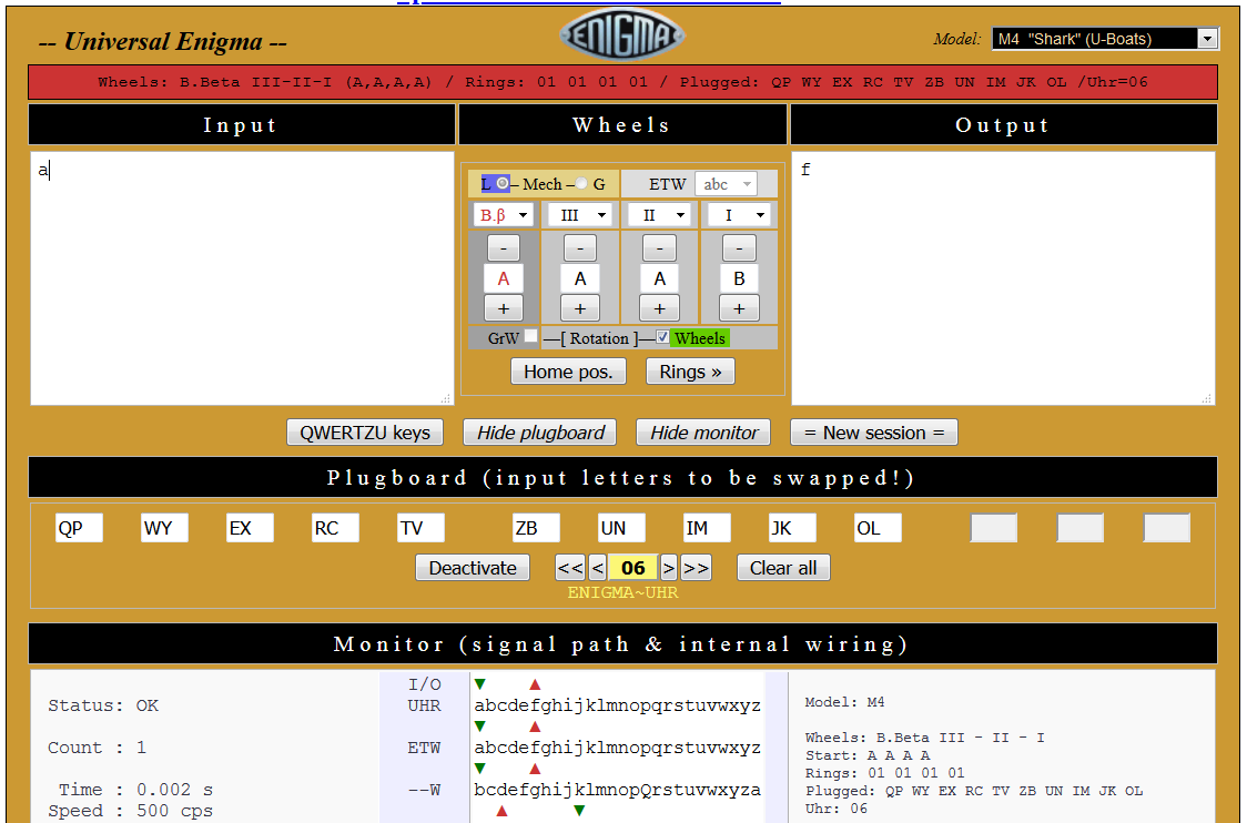
Let's use Daniel Palloks Universal Enigma to analyze how the UHR works. A default M4 machine with B reflector and Beta thin wheel has been selected. The following plugs have been installed QP WY EX RC TV ZB UN IM JK OL. The plugboard has been activated and UHR has been set to position 06
The first two lines in the signal monitor show the substitutions performed by the UHR.
abcdefghijklmnopqrstuvwxyz top
aotdxfghbvewrjczmyspnqkiul bottom
these can be expanded using the actual plug substitutions listed above (1a->8b) as shown below:
11 22 33 44 55 66 77 88 99 00
ab ab ab ab ab ab ab ab ab ab
Plugged: QP WY EX RC TV ZB UN IM JK OL top
Uhr: 06 MZ KU XI YT PQ LO NJ BR VE CW bottom
86 97 38 25 11 00 79 64 53 42
ba ba ba ba ba ba ba ba ba ba
Lets press A:
The arrows indicate the direction the signals are traveling. The topmost green arrow going down into A shows the keyboard going into the UHR, since this letter is not plugged, it goes into the ETW, the entry rotor as itself. It comes out of the rotor pack as F, and again, this letter is not wired to the UHR, so it goes out to the lamp field as itself.
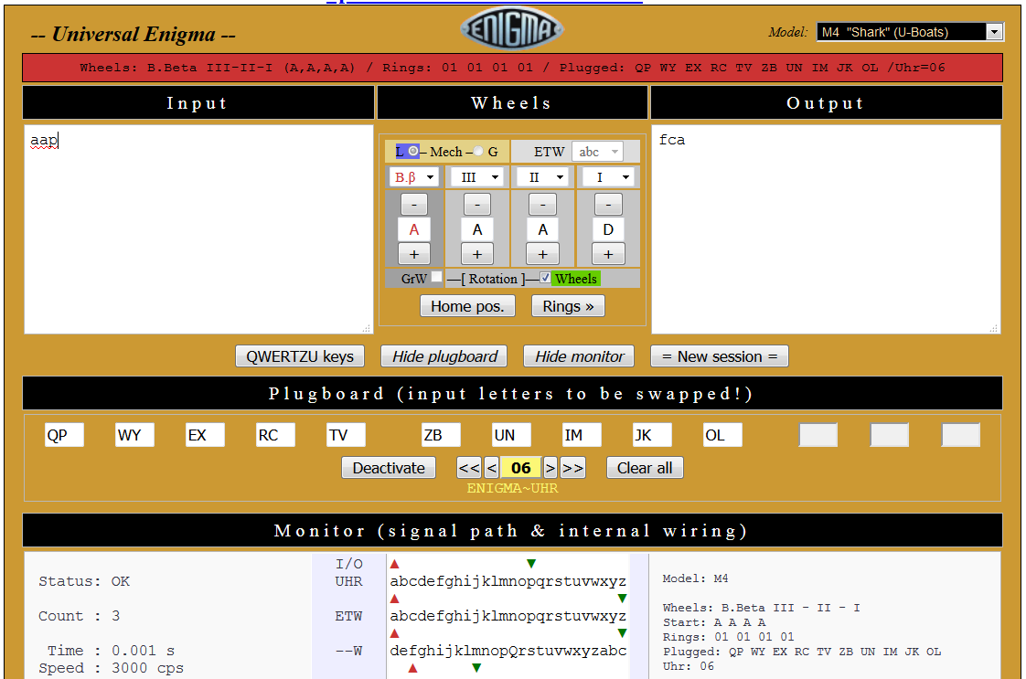
Now lets press A again.
It goes in as A, an unplugged letter, so it goes into the rotors as A, comes back out as T, a plugged letter and the UHR performs a bottom to top lookup and goes out to the lampfield as C.
Now lets press a plugged key, P:
It goes in as P, a plugged letter and the UHR performs a top to bottom lookup, sending it into the rotor pack as Z. It goes through the rotors and comes out as A, an unplugged letter, so it continues as an A to the lampfield..
Lastly, lets press P again:
It goes in as P, a plugged letter and the UHR performs a top to bottom lookup, sending it into the rotor pack as Z. It goes through the rotor pack and comes out as O, a plugged letter and the UHR performs a bottom to top lookup and goes out to the lampfield as B.
Now, lets press P until the green arrow going from the keyboard into the UHR and the red arrow coming from the rotors out into the UHR align:
P gets translated by the UHR as Z when going from the keyboard into the rotors and the resulting P gets translated by the UHR as T when going out from the rotors into the plugboard.
And this is the point where one realizes that a software implementation of the UHR switch on a simulator that has a plugboard with a single plug per letter is not a straightforward task. The UHR needs to know whether the signal is going into the rotors or coming out of the rotors.
The real enigma machine uses two connectors per plug, A normal wired plug crosses the top connector on one side to the bottom connector on the other side and vice versa. The plug has an internal shorting bar that connects to top connector and the bottom connector. The plug pushes that shorting bar with an insulated tip and connects the top and bottom of one letter to the bottom and top of another letter. The UHR connects the top side of the plugs to the bottom side of the plugs using the A and B connectors.
A software UHR with single connector per letter needs to somehow differentiate whether the signal is going into the rotors and it needs to perform a top to bottom translation or it is coming out of the rotors and into the UHR and it needs to perform a bottom to top translation.
The different substitutions have been highlighted below. The entry substitution is the highlighted P on the top left side of the diagram, that gets translated through a top to bottom lookup into a Z. The exit substitution is the highlighted P on the bottom right part of the diagram, that gets translated through a bottom to top lookup into a T.
11 22 33 44 55 66 77 88 99 00
ab ab ab ab ab ab ab ab ab ab
Plugged: QP WY EX RC TV ZB UN IM JK OL top
Uhr: 06 MZ KU XI YT PQ LO NJ BR VE CW bottom
86 97 38 25 11 00 79 64 53 42
ba ba ba ba ba ba ba ba ba ba
Another thing to keep in mind is that the UHR does not see all the letters being encoded.
A->F (A is unplugged, F is unplugged, the UHR sees neither)
A->C (A is unplugged, C is plugged, the UHR sees only the exit path)
P->A (P is plugged, A is unplugged, the UHR only sees the entry path)
P->B (P is plugged, B is plugged, the UHR sees two signals, one as an entry, one as an exit)
Furthermore, in the P->Z translation and P->T translation, the UHR sees both as P, but in one case the correct translation is Z and in the other one is T.
So, the UHR is not in a position to monitor all the letters being encoded and a letter sometimes needs to be translated as an entry signal (top to bottom) and sometimes as an exit signal (bottom to top).
An initial solution was to have a state variable in the UHR device. The first signal would be translated as top to bottom. Then when the first signal is released, activating a second signal would get translated as a bottom to top. The enigma machine would then perform two plugboard queries when a key is pressed. The first query would return the top to bottom substitution and the result would get used to send it through the rotors. The second query would be performed just to keep the UHR in sync with the enigma, its result would not get used. The letter would then get sent through the rotors and it would come out as a different letter. The output letter would be queried through the plugboard again. The first query would be translated by the UHR as a top to bottom translation and it would get disregarded by the enigma logic. The enigma logic would then query the plugboard again and the UHR would perform a bottom to top translation. The enigma logic would use that result to illuminate the lampfield. This logic works but it tends to get lost if the UHR is changed while a key in the enigma is pressed.
Since the UHR is in no position to see all the encoded letters, it needs to return the top to bottom and bottom to top translations for a given letter. A better solution is described below.
When the Enigma activates a letter in the plugboard, the UHR first activates in response the result from the top to bottom lookup. This is noticed by the pluigboard reading logic in the enigma simulator. After a period of time, the UHR releases the first response, and activates the result corresponding to the bottom to top lookup. It is up to the enigma and plugboard logic to decide whether the first or the second result gets used.
The UHR code below performs the top to bottom lookup and activates that plug
The plugboard logic detects the first and second responses and returns the one value the enigma needs
The enigma logic requests the first value going into the rotors
And the second value when going out of the rotors and into the lampfield


No comments:
Post a Comment