For more information about the UhrSwitch:
Bill of Materials:
1) 1x UHR Switch PCB
2) 1x Meduino, (Mega 2560 Pro Mini). Make sure the pins to the right and the left of the USB connector match
https://www.ebay.com/sch/i.html?_nkw=meduino
3) 2x 0.56 inch RED 7 SEGMENT LED DISPLAY COMMON CATHODE. Get either 2x 5161AS or 2x 5611AH
https://www.ebay.com/sch/i.html?_nkw=5161as
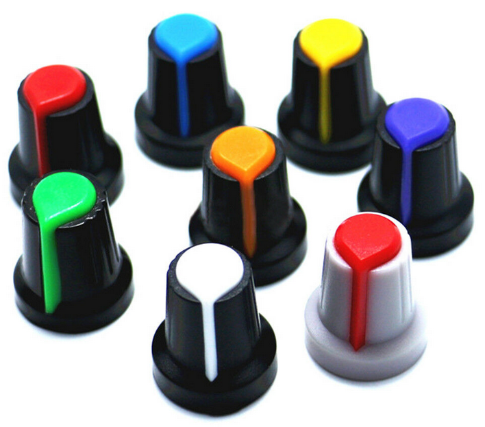
5) 1x Potentiometer Cap (you may want to substitute with something more appropriate)
https://www.ebay.com/sch/i.html?_nkw=potentiometer%20cap%206mm%20inside
7) 20x 0.5M Audio Cable 3.5mm Male to Male 90 Degree Angle. Get the 0.5M the 20cm is too short.
8) 4x M2 25mm Female to Female Brass Standoff
https://www.ebay.com/sch/i.html?_nkw=M2%2025mm%20Female%20to%20Female%20Brass%20Standoff
9) 4x M2 6mm Plastic Screw (Black)
10) 4x M2 6mm Brass Screw
11) 1x 3 Pin PCB Mount 5.5x2.1mm Female DC Power Jack Socket Connector
https://www.ebay.com/sch/i.html?_nkw=3%20Pin%20PCB%20Mount%205.5x2.1mm%20Female%20DC%20Power%20Jack%20Socket%20Connector
https://www.ebay.com/sch/i.html?_nkw=3%20Pin%20PCB%20Mount%205.5x2.1mm%20Female%20DC%20Power%20Jack%20Socket%20Connector
Component Pictures:


Assembly Steps:
Read all of the assembly steps and look at the pictures at the bottom before starting any soldering. The components can be placed in the PCB before soldering them in order to verify that everything fits and is on the correct layer. Start soldering only once everything is understood.
Identify Top and Bottom sides of PCB.
Top: only shows EXT and INT words in white
Bottom: Flag, word UHRSwitch
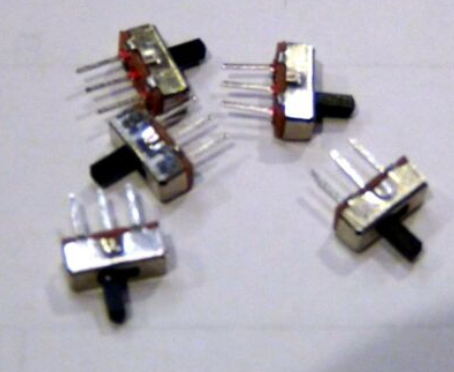
-Insert power switch on 3 pin header next to the words EXT and INT on top side of PCB and solder it.
-Insert 2x seven segment displays on headers on top side of PCB and solder them
-Insert ENC11 Rotary encoder on top side of PCB and solder it
-flip PCB to bottom side
-Insert pin headers for Meduino into bottom side of PCB. Insert the short end of the header pins into the PCB so they do not protrude too far out the front side. Flip the PCB and place on a flat surface. Solder pins on front side of PCB. Be careful not to touch the side of the seven segment displays with the soldering iron.
-Flip PCB and insert Meduino onto long side of pin header on bottom side of PCB. Solder it
-Insert PCB Spacer on DC Power Jaack and Insert Jack into bottom side of UHRSwitch PCB. The role of the Spacer is to keep the DC Power Jack pins from protruding too far out the front side of the PCB. Solder the Power Jack.
-Flip PCB to top side.
-Insert audio cables into holes on PCB from top side. The tails of the cables should point down, away from the seven segment displays.
-Flip PCB to bottom side.
-Solder one spot from the audio cable plug to the PCB.
-Once all soldering is completed, sand down any mouse bites sticking out the sides of the PCB.
Assembled Unit Pictures:

