Wednesday, January 29, 2020

Mega Enigma battery endurance test using AA batteries concluded

An endurance test was conducted to determine how long will MegaEnigma run on a set of AA batteries. A previous test determined that a set of AAA batteries kept the unit running in standby mode for 21.8 hours.


First an AA battery holder was laser cut and assembled.


The male pin to 9V battery plug adapter was made to allow an unmodified battery compartment to plug into an unmodified arduino power plug. Note the polarity of the adapter is reversed in order to correctly supply 6.4V center positive at the 9V male plug.


The self monitoring sketch was uploaded and allowed to run until the batteries could not power the unit. Then the reporting sketch was uploaded. Here is the point where the monitoring sketch stopped recording new values.


And the reporting logic correctly identifies the maximum value recorded in the buffer.


And this translates to 62.75 hours of continuous standby using fresh AA batteries on a unit with Blue 16-segment leds. A significant increase in runtime from the previously obtained 21,8 hours on a set of AAA batteries.


The next question is what will the standby time be when using White 16-segment leds.

Sunday, January 26, 2020

Mega Enigma Assembly Steps

1) Power Jack
2) Keys
3) Arduino Mega
4) 16 Segment Displays
5) Lamp Field
6) Plugboard sockets
7) Shorting PCB
8) TVS Diodes
9) Copper bus on common side of TVS Diodes
10) Header
11) Bend Header
12) Solder Plugboard Header to Main Board

Saturday, January 18, 2020

Mega Enigma Software V12 Released

This version focuses on operational realism of the enigma machine.

Sometimes, modules get a little hacky from adding features one at a time. Once all the features are defined, it is better to rewrite a function from the ground up and it comes out cleaner.

ProcessEnigma() in EnigmaGUI.ino has been rewritten, particularly case 2 in the finite state machine.

The machine has been designed to operate as follows:

Pressing a key first moves the rotors then lights up the correct result. While the rotors are moving, the contacts are not making, so nothing is illuminated.

A key must be held pressed down to illuminate a result, releasing the key turns off the lamp.

Two keys can be pressed at the same time. The way the keyboard circuit is arranged, the two top rows are in the same zone, while the bottom row is on a separate zone. The rotor up and down keys are in a separate zone. The menu key is in the same zone as the bottom row. Pushing two keys in the same zone corrupts what is displayed. Pushing keys in separate zones does not corrupt the display. Normally, only one key is pushed at a time in an enigma machine, so this zone arrangement is not part of the normal operating procedure.

If the menu key is pressed while a key is being held down and its result is illuminated in the lamp field, exiting the menu restores the current position of the rotors and the illuminated result.

While holding a key down, the rotors can be changed. The lever mechanism of the enigma machine allows each rotor to be advanced while a key is held down, but the ratchet mechanism does not allow an engaged rotor to be moved backwards while a key is pressed.

The fast rotor always turns, so if a key is pressed, it cannot be moved back to the initial position, only advanced. The middle rotors can be moved back until the stepping notch is engaged.

Changing a rotor with a key pressed down changes the output shown in the lampfield.

The plugboard is scanned dynamically. Changing a plug with a key pressed down changes the result shown in the lampfield.

The original Enigma Machine uses a two way switch in each key. If a key is not pressed, it is connected to its corresponding lamp in the lamp field. Pressing a key down connects the battery to the key and sends it to the entry rotor (ETW). The current goes through the rotor maze in and out of the reflector (UKW), and back through the rotor maze into the ETW and through an unpressed key it connects to the lamp field.

Lets use the default settings for an M4 machine with a B UKW and a Beta thin wheel and the rotors at AAAA. Pressing the V key results in E lighting up. V and E are in different zones, so both keys can be pushed down simultaneously without display corruption.

If, while holding V down, the E key is pressed, the path to the lamps would be disconnected in both ends in a real enigma machine, nothing lights up. In this simulator, this behaviour is modeled in software.

Releasing only the V key lights up the V lamp, releasing only the E key lights up the E lamp. Changing the rotors with both V and E pressed illuminates two different lamps in the lampfield. Installing or changing a plug from V or E to any other plug will illuminate two lamps in the lampfield.

So, generally, pressing a key and the key corresponding to its result simultaneously results in both lamps turning off as there is no path to the lamps.

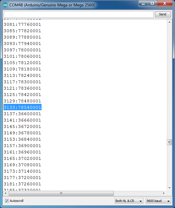
The sequence to illuminate a key in an external USB lamp field is sent out the serial port when a key is pressed.

If the Mega Enigma Machine Simulator is connected to a computer, the Arduino IDE Serial Port Monitor can be opened used to interact with the simulator.

Sending !aaaa sets the rotors to position AAAA. Sending text encodes it. Changes to the machine configuration cannot be made through the serial port, only the rotor position can be changed.

Other unchanged features are:

Holding down the menu key results in an emergency zeroisation. All the settings are cleared and returned to a default M4 machine with B UKW and Beta additional wheel. The ring is reset to AAAA and the rotor position is changed to XXXX to indicate the settings have been cleared. Any physically installed plugs would need to be removed to complete the key erasing procedure. If software plugs were in use, they are cleared. The built in UKWD is reset to 0 as well.

The menu key is ignored for a fraction of a second when the simulator exits out of the menu and returns to the operational mode. This makes it easier to not reenter the menu and stay in operational mode if the menu key is pressed rapidly to advance through the menus and exit.

A hex uploader can be downloaded below:

https://gitlab.com/arduinoenigma/megaenigma/tree/master/compiled/MegaEnigmaV12

Full Source Code:

https://gitlab.com/arduinoenigma/megaenigma/tree/master

Monday, January 13, 2020

Measuring Battery Run Time By Writing Checkpoints to EEPROM

One way to measure how long a device runs on batteries is to use another Arduino with a Light Sensitive Resistor. Can we do better than that and have the device self monitor without using any external attachments?

How to measure how long will a device run on batteries by writing time stamps to EEPROM.

The key to this algorithm is to either use an external stimuli to set a ram variable or use a different sketch to write a special variable to EEPROM to enter a special routine that writes the value of millis() to EEPROM. Once this special routine is entered, the EEPROM flag that was used to enter is cleared. This way when the device under test runs out of batteries and starts rebooting, the recording routine is not entered again. In EEPROM we will have a series of ever increasing 32 bit values. The only thing remaining is to read all the values and find the maximum. In case the device reboots while writing to EEPROM, an additional check is that the maximum value must equal to the second greatest value plus whatever the time increment used. 

In order to implement a wear leveling algotithm, the time values are written to an EEPROM zone in a circular buffer fashion.


Check out the actual code used to implement this functionality:
https://gitlab.com/arduinoenigma/megaenigma/commit/c74146f7ade4ea219ac390ada9493e9dc439daf9#a878fb2d118cf18caae6e3fd3392674ce8988b42_39_42

The timing routine was run with a used battery and the recorded values were displayed. EEPROM address 701 contains the value of millis() when the recording function was first entered, subsequent values are recorded every minute.


This 9V battery was used, so after 58 minutes, the machine rebooted and stopped recording values. The remainder of the buffer contains 0 left over from the initialization procedure.


Trying again with a fresh set of batteries. After the batteries are allowed to run down, connecting to the device shows a message stating that the endurance test has been run.


This time the test ran for a longer time. The circular buffer was configured from addresses 701 to 3501, storing a 4 byte values lets us write 700 values before reaching the end of the buffer. If a value is stored every minute, the buffer will store 11 and a half hours of data. 


Memory location 3133 contains the highest value recorded, 78540001 milliseconds or 21.8 hours. The value in 3137 is lower, indicating that the code was in its second pass over the circular buffer. By using the wear leveling algorithm, each memory location was used once or twice.


The configuration values of the timing routine were changed to use a larger buffer after the test was run. Memory locations starting at 3501 were left uninitialized at 255 and show the maximum possible number for an unsigned long.


This throws the report off. One can go back and look by hand for the tell tale incrementing values followed by a lower value.


Here are the values for the larger buffer:


If we change that to match the size of the original bufffer:


Now the report runs right and finds the correct value:


58 minutes for a used 9V battery and 21.8 hours for a fresh set of AAA batteries. A fresh 9V battery should run about 8 hours.


And the standby runtime for the Mega Enigma on a fresh set of AAA batteries is a respectable 21 hours. Pressing keys and illuminating results in the lampfield will reduce that time, but code would have to be written to simulate keypresses and illuminate results.

 Now the question is, how long will the device run on a fresh set of AA batteries. The bigger the batteries, the longer the runtime...

How to put a battery compartment inside a laser cut enclosure.


Designing the battery compartment:


A template with all the pieces for an AAA battery holder.


An AA battery holder.


The laser cut files for an enclosure:


How the battery compartment looks like 


A hex nut piece was used as the first one to allow a small piece of plastic to keep the screws captive in the lid. The actual hex nut is sandwiched further down the stack in between two pieces with small holes.


coupled with a 9V plug, a device can be powered by the built in bateries or an external 9V battery.


A two way power switch selects between the internal and external power sources. Selecting the external source when there is nothing connected or the internal source when the battery box is empty turns off the machine.


Download the design files here: