These are the specifications for the Miniature Arduino Enigma Machine Simulator.
It has been called "probably the tiniest practical digital Enigma simulation."
Machines Emulated:
Enigma I, M3, M4
Entry Contacts (ETW):
ABCDEFGHIJKLMNOPQRSTUVWXYZ
Reflectors (UKW):
A: EJMZALYXVBWFCRQUONTSPIKHGD
B: YRUHQSLDPXNGOKMIEBFZCWVJAT
C: FVPJIAOYEDRZXWGCTKUQSBNMHL
B thin: ENKQAUYWJICOPBLMDXZVFTHRGS
C thin: RDOBJNTKVEHMLFCWZAXGYIPSUQ
Rotors:
1: EKMFLGDQVZNTOWYHXUSPAIBRCJ, steps next wheel on Q-R transition.
2: AJDKSIRUXBLHWTMCQGZNPYFVOE, steps next wheel on E-F transition.
3: BDFHJLCPRTXVZNYEIWGAKMUSQO, steps next wheel on V-W transition.
4: ESOVPZJAYQUIRHXLNFTGKDCMWB, steps next wheel on J-K transition.
5: VZBRGITYUPSDNHLXAWMJQOFECK, steps next wheel on Z-A transition.
6: JPGVOUMFYQBENHZRDKASXLICTW, steps next wheel on Z-A and M-N transitions.
7: NZJHGRCXMYSWBOUFAIVLPEKQDT, steps next wheel on Z-A and M-N transitions.
8: FKQHTLXOCBJSPDZRAMEWNIUYGV, steps next wheel on Z-A and M-N transitions.
Additional Rotors (Greek Wheels):
Can only be used in M4 machines next to thin reflectors B & C. They do not step.
Beta: LEYJVCNIXWPBQMDRTAKZGFUHOS
Gamma: FSOKANUERHMBTIYCWLQPZXVGJD
The four rotor M4 machine can be made compatible with an M3 machine with a full size B reflector by selecting the thin B reflector and the Beta wheel in the A position. The M3 full size C reflector can be emulated in the M4 machine with the thin C reflector and the Gamma wheel in the A position.
Thus, the full size B and C reflectors can be redefined (re-wired) without losing compatibility with M3 machines. You will only be able to communicate with other machines with the same reflector wiring. If this academic possibility interest you, contact us for details.
Stepping Mechanism:
Levers and Notches. The middle rotor double stepping anomaly is simulated correctly. See http://arduinoenigma.blogspot.com/2014/11/some-test-cases-for-double-stepping.html
Plugboard:
Up to 13 plugs can be installed to swap the letters as they go from the keyboard to the rotor field and also when coming out from the rotor field to the lamps. When exactly 10 plugs are installed, the Uhr switch is enabled. The plugs perform a symmetrical substitution. If a plug between A and Z is installed. if A is typed, it will be converted by the plug into a Z going into the rotors. If a letter is encoded into an A, the plug will turn it into a Z going out to the lamps.
Uhr Switch:
An external attachment that connected to the plugboard via 20 plugs, 10 red (a1..a10) , 10 black (b1..b10). A big dial allowed selection of 40 settings: 00..39. Emulates traditional plugs at setting 00, performs symmetrical substitutions at settings that were multiples of 4 (4,8,12...) and different asymmetrical substitution ie: A->Z but Z->G at all other settings.
For more information: http://cryptomuseum.com/crypto/enigma/uhr/
Printer:
Yes, a paper tape runs in between the rotors and the lamp field, the tape can be cut by touching it's rightmost part. Printing groups are selectable (continuous, 4,5,6 letters). Can also be disabled for a genuine experience.
External control:
Yes, through a USB virtual serial port. The wheel position can be set and letters sent to be encoded. Encoded characters are printed in groups, if the printer option is set to 4, 5, or 6.
Keyboard layout:
Old german qwert
QWERTZUIO
ASDFGHJK
PYXCVBNML
Power:
Can be powered up with a 9V battery and the included plug or connected to the computer with a A-B usb cable (not included)
Dimensions:
(counting wood case, plywood is 3.2mm (0.126") thick)
Width: 60.9mm (2.3975")
Length:78.3mm (3.083")
Height of bottom half: 24.9mm (0.980")
Contents of Package:
-Arduino Uno R3
-Seeed Studio 2.8" TFT Touch Shield V2.0 SKU: SLD10261P
-Laser cut case, made from 3.2mm Birch plywood with engraved Enigma logo
-9V to Battery Clip to Plug Barrel Jack
-9V Battery
-Welcome message (encrypted of course)
Tuesday, January 13, 2015
Monday, January 12, 2015
Operating the Arduino Enigma Machine via Serial Port
This guide shows how to operate the Arduino Enigma Machine from a computer via serial port. The following instructions can be followed with the touchscreen simulator or with the arduino sketch provided in the post titled Source Code for implementation of Arduino Enigma Algorithm thru Serial Port.
 To start, find the Arduino logo on the desktop and double click it.
With no Arduinos plugged in, the list of existing serial ports are shown,
 After an Arduino is connected to the computer, Windows will automatically install the USB driver and assign it a serial port. Click on Tools->Port and select the new serial port.
WARNING: From here, you can upload a blank sketch to your simulator if you click the right facing arrow next to the checkmark.
If this happens to you, don't worry, simply contact us at the gmail address shown on the Contact section on the right panel.
You will receive an installer to restore the firmware for the latest enigma program on your machine.
 Once the right serial port is selected, press Ctrl+Shift+M or click on Tools->Serial Monitor
Ensure the baud rate on the lower hand right corner is set to 9600.
By default, the machine is set to verbose mode, where the actual rotor wiring and internal path is shown. The rotor types can be seen in the LCD with the machine open. The word TEST was typed. It encodes to EWVY.
 To change the machine from Verbose to Encode, first open it by clicking on the Enigma Logo.
 Once the machine is open, the reflector, rotor types, ring settings and machine configuration options can be changed.
Touch "SERIAL:" until it changes to "C"
The machine will now accept text to encode thru the serial port. The other options are NO, for no operation and V, for verbose.
The printer groups will affect how many characters are grouped together in the paper tape running above the lamp field as well as the characters returned through the serial port. The machine will now print four (4) characters, then a space.
 Once the desired configuration is set, touch the words "CLOSE" or the handle on the upper left hand corner to close the machine.
These are just the steps needed to change the serial port operation.
To see how to change all the settings of the machine, please consult the users guide.
 The settings for this example are:
Reflector C Thin
Greek Rotor Beta
Rotors 2,1,3
Plugs BL EZ IU JO MV PX RW.
To set the starting rotor position to ABGI, send !abgi. If a three rotor machine was selected, the rotors would be set to ABG and I would be encoded.Uppercase and lowercase are treated the same.
 To encode something, type in the upper text box and click "Send".
The word "TEST" is going to be sent for encoding
 Test was encoded to EWVY as shown at the bottom of the screen.
Next the words "OF THE ENIGMA MACHINE SIMULATOR" are going to be sent for encoding. Lower-case and upper-case characters are treated the same, any characters not in the Enigma Machine keyboard like numbers, symbols, space, are ignored.
 The rest of the phrase was encoded and every four (4) characters, a space was inserted. Any additional characters be added to the current line.
We are now going to change the wheel positions back to ABGI by sending !abgi
 When the wheel position is set with the ! command, a new line will be started. The string "TEST OF THE ENIGMA MACHINE SIMULATOR" was sent in one line. The result matches the line above where the phrase was sent in two parts.

With no Arduinos plugged in, the list of existing serial ports are shown,

WARNING: From here, you can upload a blank sketch to your simulator if you click the right facing arrow next to the checkmark.
If this happens to you, don't worry, simply contact us at the gmail address shown on the Contact section on the right panel.
You will receive an installer to restore the firmware for the latest enigma program on your machine.

Ensure the baud rate on the lower hand right corner is set to 9600.
By default, the machine is set to verbose mode, where the actual rotor wiring and internal path is shown. The rotor types can be seen in the LCD with the machine open. The word TEST was typed. It encodes to EWVY.


Touch "SERIAL:" until it changes to "C"
The machine will now accept text to encode thru the serial port. The other options are NO, for no operation and V, for verbose.
The printer groups will affect how many characters are grouped together in the paper tape running above the lamp field as well as the characters returned through the serial port. The machine will now print four (4) characters, then a space.

These are just the steps needed to change the serial port operation.
To see how to change all the settings of the machine, please consult the users guide.

Reflector C Thin
Greek Rotor Beta
Rotors 2,1,3
Plugs BL EZ IU JO MV PX RW.
To set the starting rotor position to ABGI, send !abgi. If a three rotor machine was selected, the rotors would be set to ABG and I would be encoded.Uppercase and lowercase are treated the same.

The word "TEST" is going to be sent for encoding

Next the words "OF THE ENIGMA MACHINE SIMULATOR" are going to be sent for encoding. Lower-case and upper-case characters are treated the same, any characters not in the Enigma Machine keyboard like numbers, symbols, space, are ignored.

We are now going to change the wheel positions back to ABGI by sending !abgi

Using the serial port, a division of duties can be established. If physical access to the machine is controlled, the person working through the serial port has operator access, where the wheels can be set and characters encoded, but internal settings cannot be changed. The person(s) that have physical access to the machine have officer access where all the settings can be changed.
Installing the Arduino IDE and Serial Port USB Drivers.
Before the Arduino Enigma Machine Simulator can be controlled from a computer, the Virtual Serial Port USB drivers must be installed. A terminal program is also needed to interact with the machine. Installing the Arduino IDE satisfies both requirements.
First, go to arduino.cc then click on Download. I selected the windows installer for version 1.5.8 of the IDE, then clicked on the file that was downloaded.
 Windows throws a security warning to make sure we intend to execute this, click "Run"
 Click on "I Agree" to Accept the License Agreement.
 We are going to leave the default options alone. Notice the second option is install USB driver.
Click "Next"
 Leave the default folder alone.
Click "Install"
 And now we wait...
 Windows shows the following security message before installing the USB drivers.
Click "Continue Anyway"
 The installation is now completed.
Click "Close"
Find the Arduino icon on the desktop and double click it.
Leave the Arduino unplugged.
Under Tools->Port you will see the existing serial ports your computer has.
Plug the Arduino board. Windows will find it, install the driver and assign it a serial port.
The new port for this Arduino device is shown.
First, go to arduino.cc then click on Download. I selected the windows installer for version 1.5.8 of the IDE, then clicked on the file that was downloaded.


Click "Next"

Click "Install"


Click "Continue Anyway"

Click "Close"
Leave the Arduino unplugged.
Under Tools->Port you will see the existing serial ports your computer has.
Plug the Arduino board. Windows will find it, install the driver and assign it a serial port.
This is a one time setup. To operate the enigma machine, continue to the next post, Operating the Arduino Enigma Machine via Serial Port
Sunday, January 4, 2015
Wood Case Assembly Instructions
These are the assembly instructions for the laser cut wood case that comes with the Arduino Enigma Machine Simulator.
Read this instruction guide completely before beginning assembly. If you have any questions, write us at the gmail address listed on the Contact section to the right of this post.
Spare cases can be purchased at our Ponoko store:
http://www.ponoko.com/showroom/ArduinoEnigma/all
Extra materials needed, not supplied in kit:
-Gorilla Glue to assemble the case
-Elmer's Glue-All to glue the Merkblatt to the upper lid
-Hair bands or twine (to keep the case together while the glue cures
-Post-it (as a shim to raise the rear part of the arduino inside the case)
-Houseworks 1131 hinge (1 pack) (miniatures.com)
-Small chain from hobby shop to hold the upper lid partially open.
 This is what the finished product will look like.
 The first step is to take out the device from an already assembled case. To do so, the left and right joints in the front panel were cut with the saw attachment in a Leatherman Multi Tool. The whole corner does not need to be destroyed, see the left corner for the amount of material to be removed. Once the corner is cut at a 45 degree angle, the front panel will pull off.
This step is optional and can be skipped.
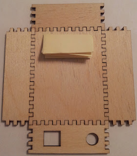 Next, arrange all the pieces for the bottom case in the correct order. The pieces can be identified by the unique shape of the corner teeth.
For the bottom half of the case, use the big piece without the laser engraved logo.
The two big pieces are identical. If you use the laser engraved one here, the logo will be hidden under the arduino and the inside of the top half of the case will be plain.
Notice the folded post-it. This is used to raise the rear part of the arduino so it sits level inside the case.
 The bottom of the arduino is not flat. The USB and power connector leads stick out from the PCB farther than the header pins. A folded post-it is used to raise the rear part of the arduino to the same height as the front.
The post-it was folded in half so that the adhesive strip was on the outside and then folded in half in the other direction two times.
The adhesive will keep it in place once the case is assembled.
 Now is the time to test-fit the case to the arduino. At this point, a hair band was used to squeeze the pieces in to make sure there are no gaps in the corner joints.
No way to avoid the camera reflection in the glass. Can you identify the camera model?
 A corner shot, everything is fitting tight and neat.
 Next, the wood needs to be moist for the Gorilla Glue to work properly. Put enough water in a disposable plate to completely cover the teeth. We do not want to get this whole piece wet, the arduino sits in it. The arduino should not be powered up for at least two hours after the case is glued to allow the wood to dry.
One at a time, moist all the fingers in all the pieces. Keep the fingers submerged for about 30 seconds.
Tip: by scraping the wood piece against the plate while it is submerged, the laser burn marks are removed.
 As the pieces are wetted, they get returned back to their position.
At this point, a chain will be nailed down into the left piece. The other end will be nailed later into the upper piece and it will hold it partially open.
The nail needs to be above the touchscreen PCB. Test fit the case around the pcb to determine the depth of the pocket. The pocket has been measured to be 3.2mm deep. The nail can be driven 2mm to the right of the edge.
The nail will go where the red star is shown on the left piece.
 Another test fit with the moist pieces, to ensure everything still fits.
 We are using Gorilla Glue. It is similar to Elmer's wood glue. They both need the surfaces to be moist to work and expand while curing.
 There is no going back now, apply a thin bead of glue to the inside of the teeth of the four side pieces. Do not worry about the space in between teeth, this glue expands.
Do not apply glue to the bottom piece. The four side pieces will glue to it.
The front panel is shown after glue is applied. The other three side pieces will look the same. As each piece is glued, put them back in their position.
Do not get glue on the LCD screen. If the protector film is still applied, you are in good shape. If not, clean it immediately.
 Apply a lot of hair bands or twine to keep the case from expanding apart. The glue will expand and try to push the joints open. Keep the case like this for two hours after the glue is applied. This will allow the glue to cure and the wood to dry.
 How the underside of the case looks while the glue is setting.

 A corner shot showing the joints are tight and how the logo looks.
 Showing how the lower case pieces fit together.
The floor plate on the lower case will have an engraved enigma logo that will be hidden from view.
 Showing how the upper pieces fit together. You will receive two pieces with the engraved enigma logo, one small, one large. Shown here is the small logo. At the bottom of the post, a case with the big logo is shown. Select one that will be visible. The other unwanted one will be used as the floor plate on the lower case and will be hidden.
 The pocket for the hinges was filed down by hand in this prototype. You will receive a laser cut piece. The case at the bottom of the post was assembled with all laser cut pieces.
The hinges shown are Houseworks 1131
http://www.miniatures.com/Gold-Plated-Brass-H-Hinge-by-Houseworks-P17628.aspx
 Grab a nail with some fine tip pliers.
 Another shot showing how the nail is held.
 Place the hinge into the pocket and drive the nail down into the plywood. It will go into the middle layer and will go in smoothly. Be careful to drive it down vertically so it does not split the wood.
 The upper hinges are installed.
 Align the top part with the bottom case and drive the nails down. Be careful with the glass screen, protect it, The hand that is used to hold the bottom case in place can go over the screen to protect it.
At this point, the other end of the chain can be nailed to the inside of the left side of the upper lid. See the bottom picture for details.
 Showing the rear of the case.
 Showing how the hinges fit in a pocket and the alignment of the upper and lower pieces.
A fully assembled Arduino Enigma Simulator. The attachment point for the chain on the lower case is shown.
 Another assembled Enigma Simulator, serial Had 0001, entered in the Hackaday best product prize competition.
This one shows the Merkblatt (Instruction sheet) glued to the inside of the upper lid.
A serialized Merkblatt ships out with all simulators.
Read this instruction guide completely before beginning assembly. If you have any questions, write us at the gmail address listed on the Contact section to the right of this post.
Spare cases can be purchased at our Ponoko store:
http://www.ponoko.com/showroom/ArduinoEnigma/all
Extra materials needed, not supplied in kit:
-Gorilla Glue to assemble the case
-Elmer's Glue-All to glue the Merkblatt to the upper lid
-Hair bands or twine (to keep the case together while the glue cures
-Post-it (as a shim to raise the rear part of the arduino inside the case)
-Houseworks 1131 hinge (1 pack) (miniatures.com)
-Small chain from hobby shop to hold the upper lid partially open.


This step is optional and can be skipped.

For the bottom half of the case, use the big piece without the laser engraved logo.
The two big pieces are identical. If you use the laser engraved one here, the logo will be hidden under the arduino and the inside of the top half of the case will be plain.
Notice the folded post-it. This is used to raise the rear part of the arduino so it sits level inside the case.

The post-it was folded in half so that the adhesive strip was on the outside and then folded in half in the other direction two times.
The adhesive will keep it in place once the case is assembled.

No way to avoid the camera reflection in the glass. Can you identify the camera model?


One at a time, moist all the fingers in all the pieces. Keep the fingers submerged for about 30 seconds.
Tip: by scraping the wood piece against the plate while it is submerged, the laser burn marks are removed.

At this point, a chain will be nailed down into the left piece. The other end will be nailed later into the upper piece and it will hold it partially open.
The nail needs to be above the touchscreen PCB. Test fit the case around the pcb to determine the depth of the pocket. The pocket has been measured to be 3.2mm deep. The nail can be driven 2mm to the right of the edge.
The nail will go where the red star is shown on the left piece.


Do not apply glue to the bottom piece. The four side pieces will glue to it.
The front panel is shown after glue is applied. The other three side pieces will look the same. As each piece is glued, put them back in their position.
Do not get glue on the LCD screen. If the protector film is still applied, you are in good shape. If not, clean it immediately.


After a minimum of two hours, the hair bands are removed. The case joints are tight and the arduino powers up.
|


The floor plate on the lower case will have an engraved enigma logo that will be hidden from view.


The hinges shown are Houseworks 1131
http://www.miniatures.com/Gold-Plated-Brass-H-Hinge-by-Houseworks-P17628.aspx


At this point, the other end of the chain can be nailed to the inside of the left side of the upper lid. See the bottom picture for details.


A fully assembled Arduino Enigma Simulator. The attachment point for the chain on the lower case is shown.


This one shows the Merkblatt (Instruction sheet) glued to the inside of the upper lid.
A serialized Merkblatt ships out with all simulators.
Subscribe to:
Posts (Atom)