The seven segment displays required for previous projects had, on rare occasions, defective segments. In order to test them all, some contraptions were devised.
Here is a calculator without the displays soldered. Testing the display involved inserting the display in the PCB and running a special program that cycles through all the digits.

This is another rig to test a single seven segment display for the Art Installation Project. This one simply illuminates all the digits simultaneously. The Arduino UNO is simply providing 5V and all the digits are hardwired with jumper wires.

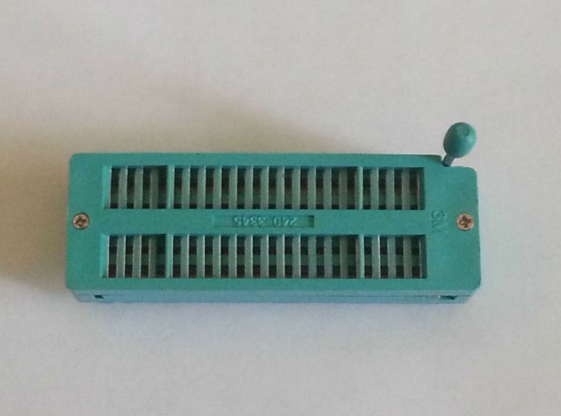
Most of the Led listings on AliExpress shows the displays being tested on some sort of ZIF socket. We will set to build something that works like that.

The following socket was found:
Here is the datasheet for the socket, we'll design a PCB based on these dimensions and adjust it later if needed.

And here is a preliminary PCB design. It is a very simple design where the bottom 9 pins on the socket are connected to an Arduino Nano.


Here is a preliminary design for a laser cut base. This design shares an edge between two pieces to minimize laser cutting time and therefore cost.

Once the socket arrives, the design for the tester and its base will be finalized. This will be a low cost tester, notice only the bottom 9 pins are wired, and that is good enough for the 16 segment displays. A later design might use the Mega Pro Mini and wire all the segments in the socket.