Started working on en Enigma UHR switch. This needs a rotary encoder to simulate the original 40 position switch.
https://www.cryptomuseum.com/crypto/enigma/uhr/index.htm
Jumped on eBay, searched for "ec11 encoder" and quickly decided on a 20 step rotary encoder. A few days later it showed up in the mail.
From previous work on rotary encoders, I remembered they have a common pin, and two pins that produce a square wave that's out of phase. If the pins are read together they are supposed to return a sequence like 11->10->00->01. This is called Grey Code, where two successive states only differ by 1 bit.
One side of the switch has 3 pins the other side 2. The two pins on one side get shorted together when the shaft is pushed. The three pins on the other side are the rotary encoder pins. The data sheet says that the center one is the common and the other two produce the out of phase square waves.
Before wiring anything, I decided to test continuity with a meter. The two pins measure open at rest and continuity when the encoder shaft is pushed in. That was easy enough. The rotary encoder pins were a different story, nothing measured continuity, rotating it did not help, measuring resistance, the meter briefly jumped from open, but it never showed continuity. Thinking that this encoder must be bad, I measured another, but got the same result.
Ok, time to wire them up to an Arduino and see what the pins are doing. The datasheet says to connect the outside pins to VCC using a 10k resistor and connect the middle pin to ground.
Jumpers were soldered to the encoder leads. The center pin, in green was connected to ground. The left and right pins were connected directly to D12 and D11. The Atmel/Microchip ATmega 328p used in the Arduino Nano has internal pull-up resistors that are activated by setting a pin as input and then writing high to it.Reading the pin will then return 1 if not connected to anything, or 0 if connected to ground.

The first step is to see what the pins are doing as seen by the Arduino. The code below uses the following fast pin library
https://github.com/mikaelpatel/Arduino-GPIO
 #include "GPIO.h"
 GPIO<BOARD::D11> PlugJ;
 GPIO<BOARD::D12> PlugK;
 GPIO<BOARD::D13> LAMP;
 void allPlugsInput()   /*xls*/
 {
  PlugJ.input();
  PlugK.input();
  PlugJ.high();
  PlugK.high();
 }
 void setup() {
  // put your setup code here, to run once:
  Serial.begin(9600);
  LAMP.low();
  LAMP.output();
  allPlugsInput();
 }
 void showrawpins()
 {
  byte EncA = PlugJ.read();
  byte EncB = PlugK.read();
  Serial.print(EncA);
  Serial.println(EncB);
 }
 void flashD13()
 {
  static int lamptimer = 0;
  lamptimer++;
  if (lamptimer > 256)
  {
   LAMP.low();
  }
  else
  {
   LAMP.high();
  }
 }
 void loop() {
  // put your main code here, to run repeatedly:
  flashD13();
  showrawpins();
 }
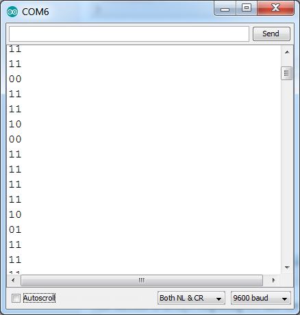
This is the output from this code

This encoder is always outputting 11, turn the shaft and some digits change, but it always returns to 11.
Scrolling up, we see that the pins change when turned.
Let's add some code to filter out the at-rest 11 state and see whats going on more clearly.
When the input pins are not showing 11, this function prints their values. When the pins return to 11, it prints "done" once and goes back to listening for a change.
 void showrawenc()
 {
  byte EncA = PlugJ.read();
  byte EncB = PlugK.read();
  static byte changing = 0;
  if (EncA + EncB != 2)
  {
   Serial.print(EncA);
   Serial.println(EncB);
   changing = 1;
  }
  else
  {
   if (changing == 1)
   {
    Serial.println(F("done"));
    changing = 0;
   }
  }
 }
Here is the output from calling this function in loop()
The encoder is being turned clockwise (CW)

And here we see the encoder being turned counter-clockwise (CCW)

Now, a pattern begins to emerge.
This encoder is always outputting 11, when turned clockwise, it starts emitting a lot of 10, followed by a single 00, before returning to 11
When turned counterclockwise, it starts with 01, then 00, then 11.
Turning the shaft rapidly shortens the initial repeat pulses, but most of the time it keeps the 00, followed by 11.

We need a function that looks for an initial 10 after 11, disregarding any other values until 11 is returned again. Report a single clockwise event. If an initial 01 is read after 11, disregard any other values until 11 is returned again. Report a single counter-clockwise event.
To keep this short, here is the final debounced routine.
It reads the encoder pins either one at a time using the read() function or both at the same time accessing PINB.
It sits in state 0, disregarding input 11 until that changes. If the first value is 10 it sets the direction to 1 and jumps to state 1. If the first value is 01, it sets the direction to -1 and jumps to state 1. In the meantime, the function is constantly returning 0. A direction cannot be reliably detected until a 00 value is read in state 1, the direction value is returned once and cleared out. When a 11 is read, the function jumps to state 0, and re-arms itself to look for the initial direction value.
 //debounced rotary encoder logic
 signed char rotaryencoder()
 {
  static byte state = 0;
  static signed char dir = 0;
  signed char v = 0;
  //read pins one at a time
  //byte EncA = PlugJ.read(); //EncA must be input() and high()
  //byte EncB = PlugK.read(); //EncB must be input() and high(), connect C to ground
  byte ENC = PINB;        //read both pins at a time
  byte EncA = (ENC & 0x08) >> 3; // isolate bit (&) 0x08 = D11 and shift right to turn into 1 or 0
  byte EncB = (ENC & 0x10) >> 4; // 0x10 = D12
  switch (state)
  {
   case 0:
    {
     if (EncA + EncB != 2) // at rest encoder outputs 11
     {
      if (EncA == 1)    // followed by many 10 when turning right
      {
       dir = 1;
       state = 1;     // detect the rising edge and then wait until it goes 00 then back to 11
      }
      if (EncB == 1)    // followed by many 01 when turning left
      {
       dir = -1;
       state = 1;
      }          // if output is 00, we missed 01 or 00, stay in this state
     }
     break;
    }
   case 1:
    {
     // once we react to the first 01 or 10, many more, followed by 00 will follow
     if (EncA + EncB == 0) // after initial 10 or 01, we must have a 00 to confirm it was valid
     {
      v = dir;
      dir = 0;
     }
     if (EncA + EncB == 2) // once we see 11 again, the encoder is idle, go back to detecting a change
     {
      state = 0;
     }
    }
  }
  return v;
 }
This function represents several improvements over its initial implementation. The first improvement was to add logic to stay in state 0 if 00 was the first value read after 11. This worked fine when turning the shaft slowly. Turning the shaft quickly resulted in the routine reporting the opposite direction sometimes.
These missed events were further filtered out with the second improvement, looking for a 00 value in state 1. A good turning event is as follows 11->01->00->11
The routine as shown above is very stable and correctly reports slow or fast turns in either direction without using any external filtering components such as resistors or capacitors or combinations thereof.
The main loop is as follows:
 void loop() {
  // put your main code here, to run repeatedly:
  flashD13();
  //showrawpins();
  //showrawenc();
  static byte uhr = 0;
  signed char v = rotaryencoder();
  uhr += v;
  if (v != 0)
  {
   Serial.println(uhr);
  }
 }
Here is an example of the encoder being rotated very fast in a clockwise direction. There is a single mis-read event at the 10-11 mark, but it will be masked by successive events, the user should not notice as the end value (18) is significantly higher than the initial value of 1. Turning the knob slowly produces corrects results all the time. Reading noisy rotary encoders is tricky, but the polling code shown above does a fairly good job of counting valid events while disregarding noise that could result in the encoder being read as being turned in the opposite direction.

Some closing notes:
Before introducing complexity in your designs, in the form of external components or complicated code, first try to understand the component you are working with. Observe its raw output, then write code to handle most of the cases. Finally, refine the code by adding more cases until it works with an acceptable percentage of reliability.
Use your internal pull up resistors. Configuring a pin as input and writing high to it, enables internal pull up resistors. This simplifies the external circuitry.
The above code implements a state machine to turn the following inputs 11->01->noise->00->noise->11 into a single valid turning event in a simple polling routine without using an interrupt service routine (ISR). The code can be expanded to keep track of multiple rotary encoders by changing the way the state variable is stored, but that is left as an exercise to the reader ;)
No comments:
Post a Comment